Check patentability & draft patents in minutes with Patsnap Eureka AI!

Power supply control system

a power supply control and control system technology, applied in the field of power supply control systems, can solve the problems of wasteful consumption of battery power, difficulty in replacing fuse parts in compact apparatus such as image capture apparatuses, etc., and achieve the effect of suppressing the consumption of power supplies

Inactive Publication Date: 2010-10-07
CANON KK
View PDF9 Cites 4 Cited by
  • Summary
  • Abstract
  • Description
  • Claims
  • Application Information

AI Technical Summary

Benefits of technology

Enables abnormal current detection without fuses and reduces power consumption by switching to a sleep mode when the battery lid is open, preventing wasteful battery drain and abnormal current flow.

Problems solved by technology

However, because an abnormal current cannot be monitored while the power supply control system is in a sleep state, a fuse must be inserted in the power supply line.
It is difficult and inconvenient to replace a fuse in a compact apparatus such as an image capture apparatus.
However, when the power supply control system is always kept in a normal state, it wastefully consumes the power of the battery.

Method used


Image

  • Power supply control system
  • Power supply control system
  • Power supply control system

Examples


Embodiment Construction

[0017]A preferred embodiment of the present invention will be described below with reference to the accompanying drawings.

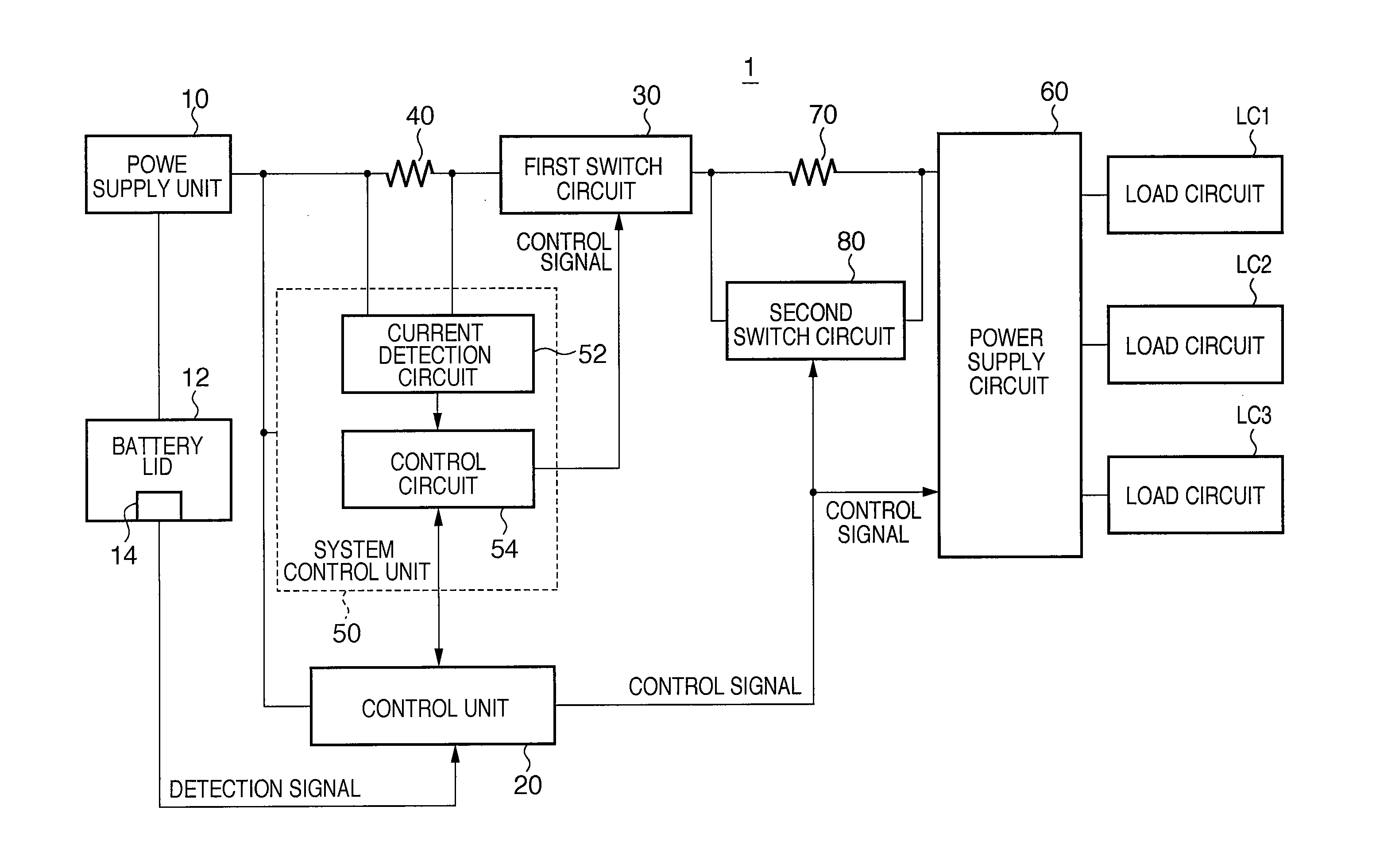
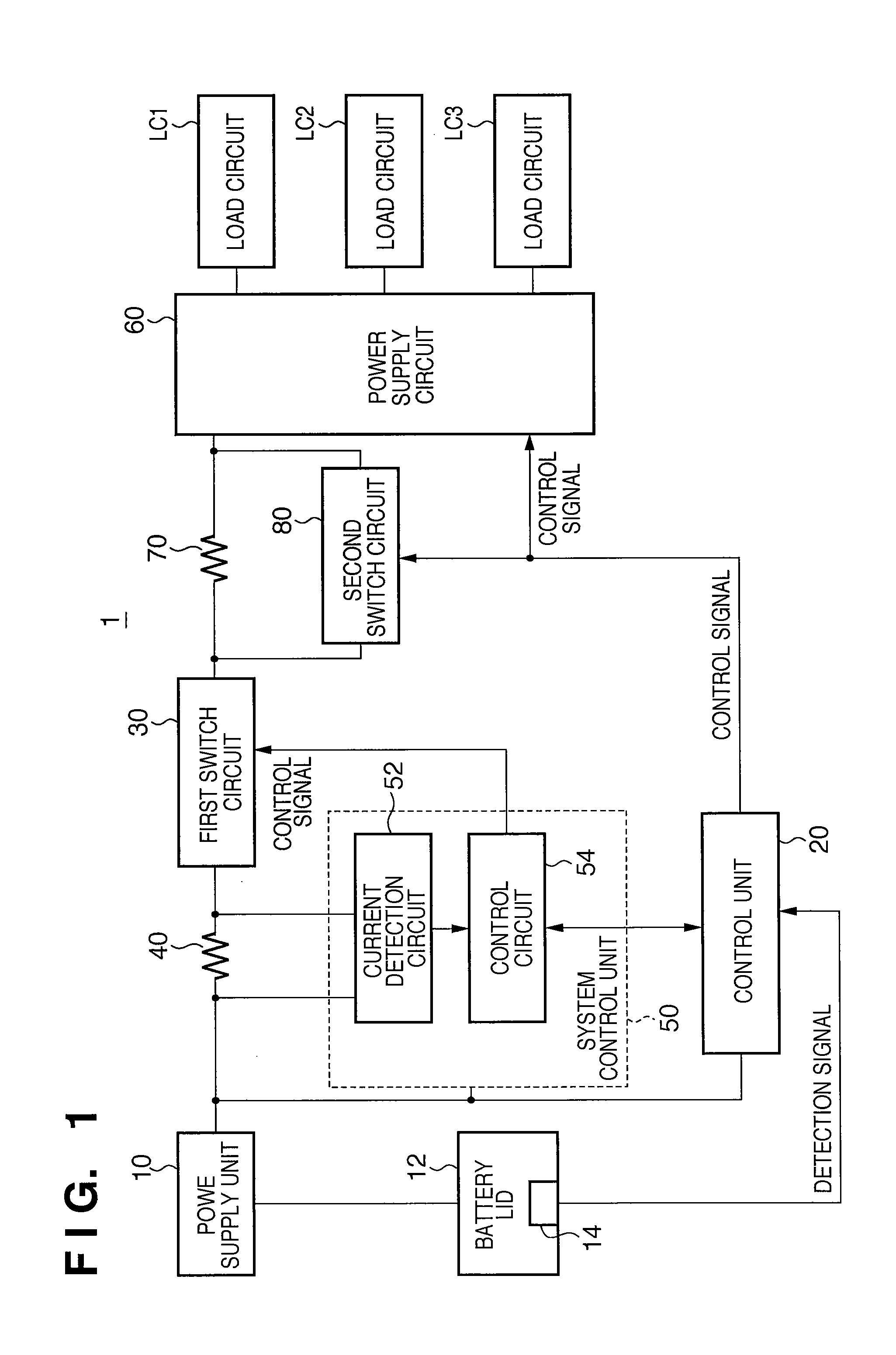
[0018]FIG. 1 is a schematic block diagram showing a power supply control system 1 according to one aspect of the present invention. The power supply control system 1 controls power supply voltages supplied to a plurality of load circuits LC1, LC2, and LC3, and is suitable for image capture apparatuses such as a digital camera. The plurality of load circuits LC1, LC2, and LC3 include, for example, a circuit for driving an optical lens, that for driving an electronic flash, and that for operating an image capture element. However, the power supply control system 1 is applicable not only to image capture apparatuses but also to various electronic apparatuses.

[0019]As shown in FIG. 1, the power supply control system 1 includes a power supply unit 10, battery lid 12, control unit 20, first switch circuit 30, current detection resistance 40, system control unit 50, pow...


PUM


Abstract

The present invention provides a power supply control system comprising a first switch circuit configured to set a power supply line which connects a power supply unit and a power supply circuit to one of a connected state and a non-connected state, a first control unit configured to operate in one of a normal mode and a sleep mode in which a consumption current is smaller than in the normal mode, and to detect a magnitude of a current flowing into the first switch circuit and control an operation of the first switch circuit based on the detected magnitude of the current while operating in the normal mode, and a second control unit configured to control an operation of the first control unit based on the detection result of an opening-closing state detection unit configured to detect an opening-closing state of a battery lid provided to the power supply unit.

Description

CROSS-REFERENCE TO RELATED APPLICATIONS[0001]This application is a continuation of application Ser. No. 12 / 188,348, filed Aug. 8, 2008 the entire disclosure of which is hereby incorporated by reference.BACKGROUND OF THE INVENTION[0002]1. Field of the Invention[0003]The present invention relates to a power supply control system which controls a power supply voltage supplied from a power supply unit to a load circuit.[0004]2. Description of the Related Art[0005]In recent years, a digital camera and digital video camera are becoming prevalent as image capture apparatuses. These cameras form an image of light from an object on an image capture element via an optical lens, thereby capturing and recording a digital image of the object. Such image capture apparatuses include a power supply control system which controls power supply voltages supplied to load circuits such as a circuit for driving the optical lens and that for operating the image capture element (see Japanese Patent Laid-Ope...

Claims


Application Information

Patent Timeline
Patent Type & Authority Applications(United States)
IPC IPC(8): H02H3/00
CPCH02J9/005Y02B70/30Y04S20/20
Inventor CHISHIMA, YUKI
Owner CANON KK
Features
  • R&D
  • Intellectual Property
  • Life Sciences
  • Materials
  • Tech Scout
  • Unparalleled Data Quality
  • Higher Quality Content
  • 60% Fewer Hallucinations
Learn More