Magnetic Device Formed with U-Shaped Core Pieces and Power Converter Employing the Same

a technology of magnetic devices and power converters, applied in the field of magnetic devices, can solve problems such as introducing a high level of power loss

Active Publication Date: 2010-10-07
POWER SYST TECH
View PDF109 Cites 57 Cited by
  • Summary
  • Abstract
  • Description
  • Claims
  • Application Information

AI Technical Summary

Benefits of technology

[0008]These and other problems are generally solved or circumvented, and technical advantages are generally achieved, by advantageous embodiments of the present invention, including a magnetic device formed with U-shaped core pieces employable in a power converter, and a method of forming the same. In one embodiment, the magnetic device includes a rectilinear core piece formed of a magnetic material, and first and second U-shaped core pieces positioned on the rectilinear core piece. The magnetic device also includes first and second conductive windings formed about the first and second U-shaped core pieces, respectively.

Problems solved by technology

Designs with such winding structures do not utilize the horizontal walls of the “E” or the “I” core pieces of the magnetic core, and accordingly introduce a high level of power losses.

Method used


Image

  • Magnetic Device Formed with U-Shaped Core Pieces and Power Converter Employing the Same
  • Magnetic Device Formed with U-Shaped Core Pieces and Power Converter Employing the Same
  • Magnetic Device Formed with U-Shaped Core Pieces and Power Converter Employing the Same

Examples


Embodiment Construction

[0015]The making and using of the present exemplary embodiments are discussed in detail below. It should be appreciated, however, that the present invention provides many applicable inventive concepts that can be embodied in a wide variety of specific contexts. The specific embodiments discussed are merely illustrative of specific ways to make and use the invention, and do not limit the scope of the invention.

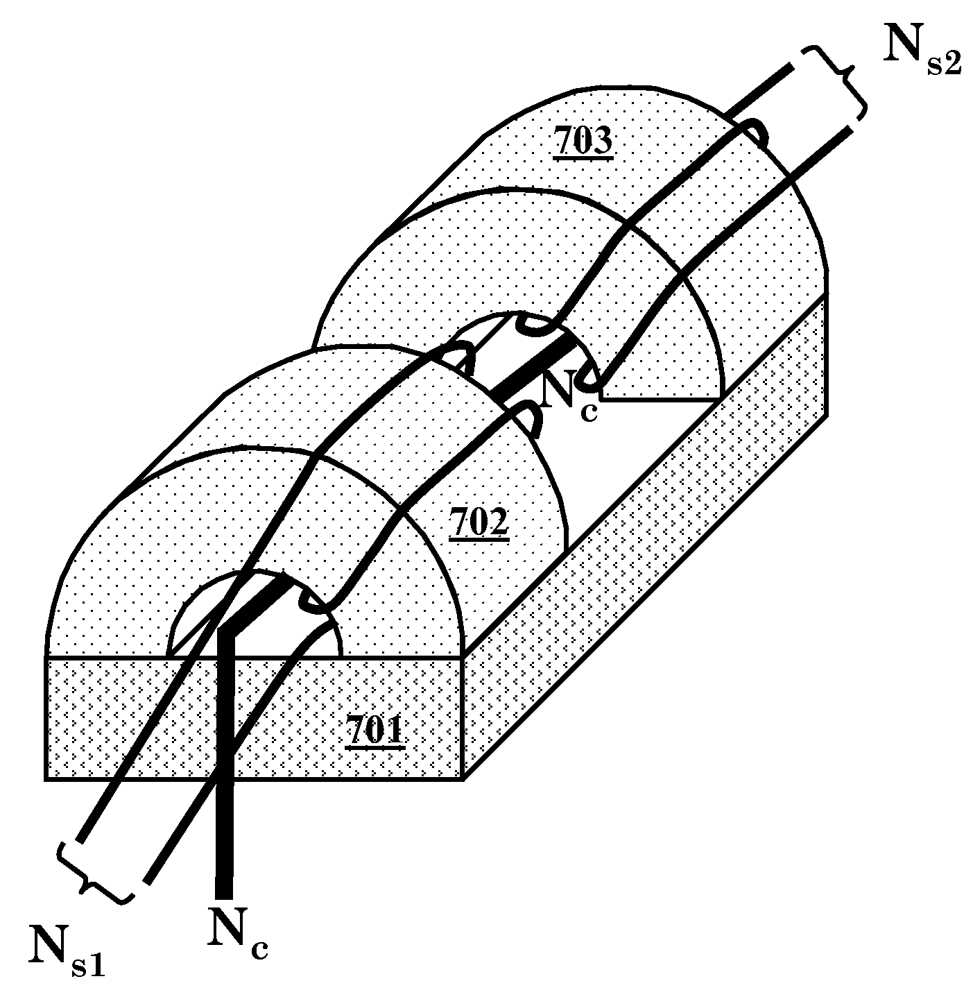
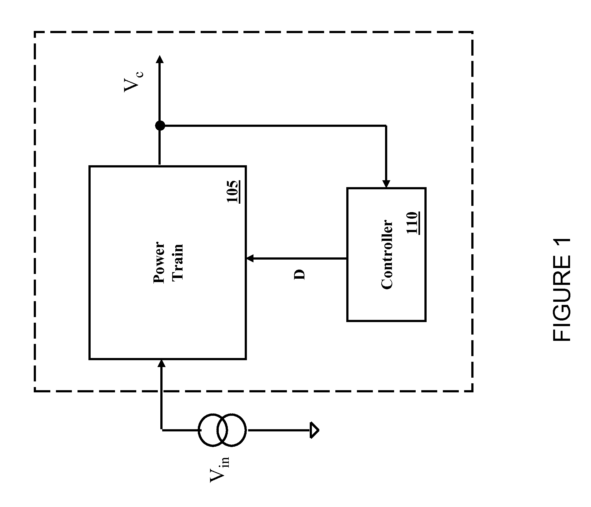
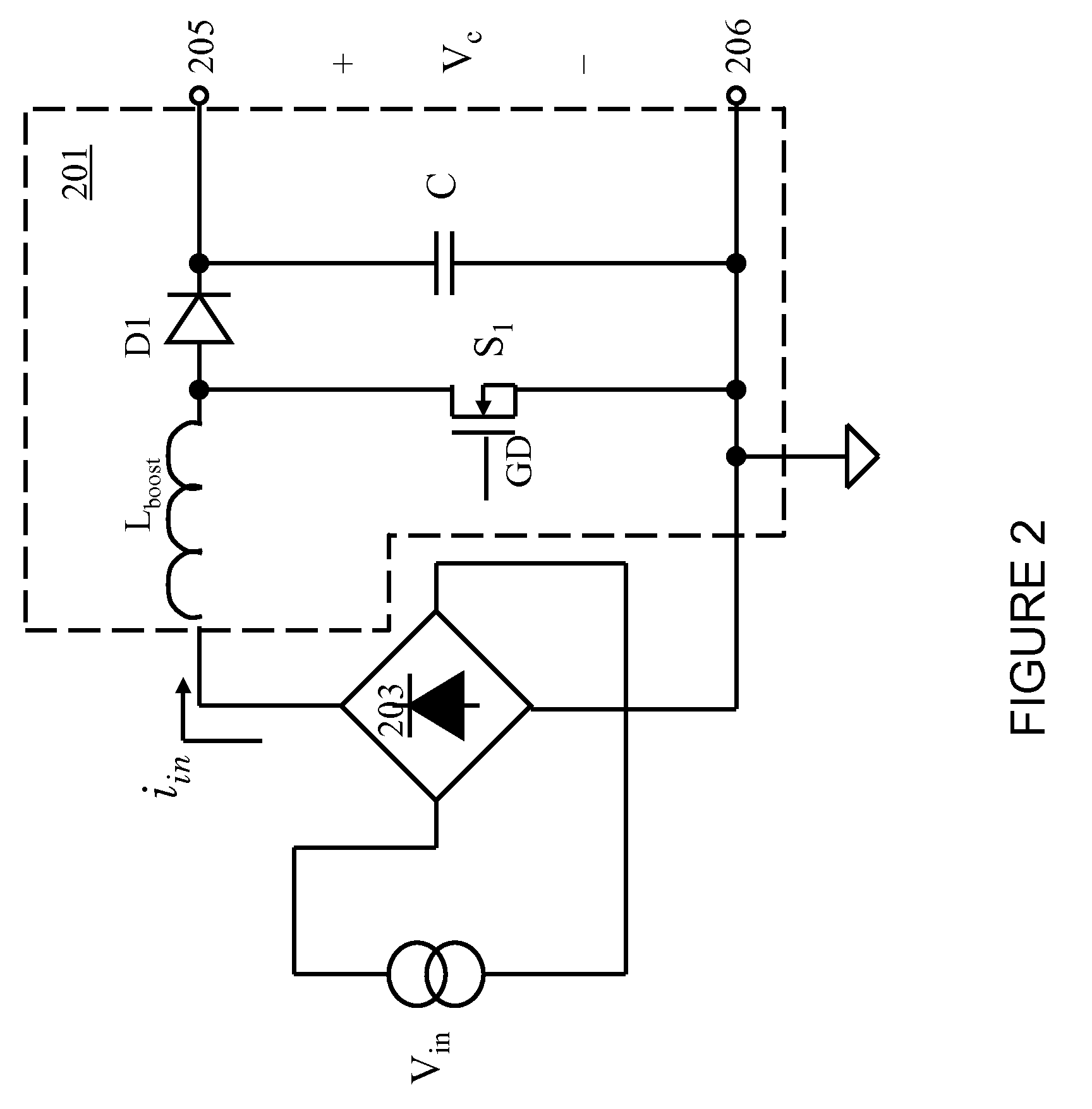
[0016]The present invention will be described with respect to exemplary embodiments in a specific context, namely, a magnetic device including a U-shaped core piece, and a method of forming the same. The magnetic device including a U-shaped core piece provides improved power conversion efficiency by accommodating a larger physical space for turns of a single-layer winding of a conductive material formed thereabout. While the principles of the present invention will be described in the environment of a magnetic device for a power converter, any application that may benefit from ...


PUM

PropertyMeasurementUnit
conductiveaaaaaaaaaa
lengthaaaaaaaaaa
relative permeabilityaaaaaaaaaa

Abstract

A magnetic device formed with U-shaped core pieces employable in a power converter, and a method of forming the same. In one embodiment, the magnetic device includes a rectilinear core piece formed of a magnetic material, and first and second U-shaped core pieces positioned on the rectilinear core piece. The magnetic device also includes first and second conductive windings formed about the first and second U-shaped core pieces, respectively.

Description

[0001]This application claims the benefit of U.S. Provisional Application No. 61 / 165,184, entitled “Magnetic Device Formed With U-Shaped Core Pieces and Power Converter Employing The Same,” filed on Mar. 31, 2009, which application is incorporated herein by reference.TECHNICAL FIELD[0002]The present invention is directed, in general, to power electronics and, more specifically, to a magnetic device employable in a power converter.BACKGROUND[0003]A switched-mode power converter (also referred to as a “power converter” or “regulator”) is a power supply or power processing circuit that converts an input voltage waveform into a specified output voltage waveform. DC-DC power converters convert a direct current (“dc”) input voltage into a dc output voltage. Controllers associated with the power converters manage an operation thereof by controlling the conduction periods of power switches employed therein. Generally, the controllers are coupled between an input and output of the power conv...

Claims


Application Information

Patent Timeline
Patent Type & Authority Applications(United States)
IPC IPC(8): H01F27/24H01F27/28H01F27/26H02M5/45
CPCH01F3/10H01F3/12H01F3/14H01F27/263H01F30/06H01F37/00Y10T29/4902H01F2038/026H02M1/4208H02M3/1582H02M2003/1586Y02B70/126H01F41/02H02M3/1586Y02B70/10
Inventor CHANDRASEKARAN, SRIRAM
Owner POWER SYST TECH
Why Eureka
Try Eureka