Image shake correction apparatus and image pickup apparatus

a technology of image shake and correction apparatus, applied in the field of image shake correction apparatus and image pickup apparatus, can solve the problems of not being able to describe the calculation calculation for correcting a focus shake, the algorithm for the calculation may be extremely complicated, and the effect of accurate image shake correction

Inactive Publication Date: 2010-10-07
CANON KK
View PDF2 Cites 22 Cited by
  • Summary
  • Abstract
  • Description
  • Claims
  • Application Information

AI Technical Summary

Benefits of technology

[0016]The present invention has been made in view of the above-mentioned problem, and therefore has an object to provide an apparatus and a method which allow accurate image shake correction in which control thereof does not fail no matter how an angle shake and a parallel shake coexist, and therefore are capable of reducing an amount of calculation.

Problems solved by technology

However, the image taking magnification used for taking a close-up image of a flower or the like is extremely large, which does not allow ignoring the influence of the parallel shake.
H07-225405 raises a problem that an enormous amount of calculation is necessary to obtain the amount of the shake in the image plane and that an algorithm for the calculation may be extremely complicated.
Further, there is no description of calculation for correcting a focus shake.
However, the model and the equation present such a problem as described in the paragraph “0047” of Japanese Patent Application Laid-Open No. 2004-295027.
It is also possible to calculate a correction amount by using outputs from the two acceleration sensors, but its accuracy is low, and an enormous amount of the calculation is necessary.
Further, the equation described in Japanese Patent Application Laid-Open No. 2004-295027 is not capable of calculating a focus shake.

Method used


Image

  • Image shake correction apparatus and image pickup apparatus
  • Image shake correction apparatus and image pickup apparatus
  • Image shake correction apparatus and image pickup apparatus

Examples


first embodiment

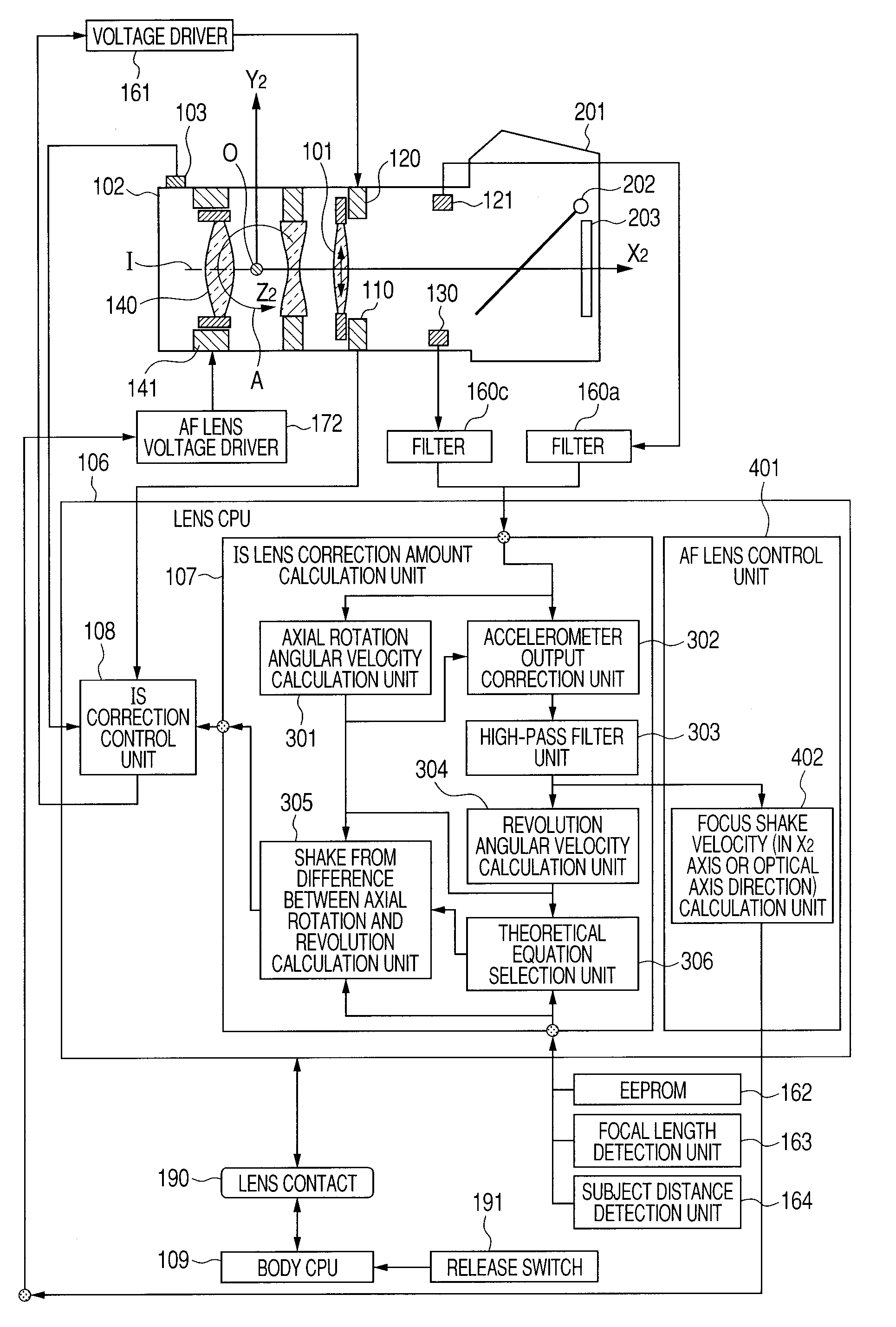
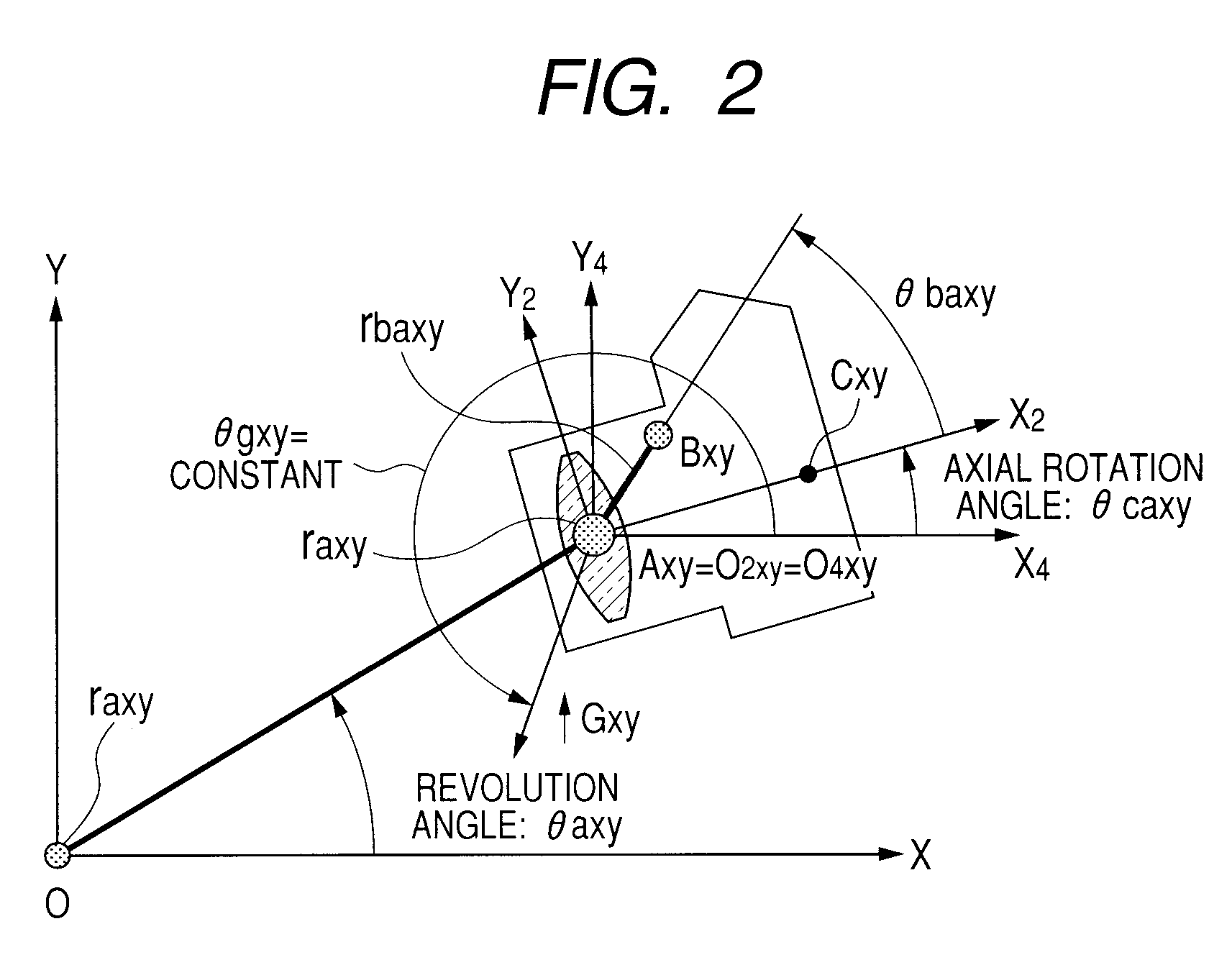
[0039]In the following embodiment, a shake movement of a camera held with a hand of a person and an image shake movement generated on an image plane as a result of the shake movement of the camera are expressed by an “axial-rotation-and-revolution shake equation” that is a merger between a movement model for expressing the movement by an axial rotation movement and a revolution movement and a geometrical-optical equation.

[0040]This embodiment relates to an image shake correction apparatus for calculating a camera shake movement from measured values of an accelerometer and an angular velocity sensor and the axial-rotation-and-revolution shake equation and further calculating the image shake movement. Then, a part of image taking lenses or a part or all of image pickup elements are controlled to be driven based on a calculated value of the image shake movement to thereby correct a shake of an image. Alternatively, the image shake correction apparatus corrects the shake of the image by...

second embodiment

[0191]With reference to FIGS. 15A and 15B, the second embodiment is described. FIGS. 15A and 15B have the same flow as FIGS. 3A and 3B according to the first embodiment. Hence, the same steps are denoted by the same reference symbols, and description thereof is omitted.

[0192]In FIGS. 15A and 15B, after the revolution angular velocity calculation in S1100, the procedure advances to S2610. In S2610, it is determined whether or not the image taking magnification is equal to or larger than 0.2 (equal to or larger than a predetermined value). If the image taking magnification is equal to or larger than 0.2, the procedure advances to S2620. If the image taking magnification is smaller than 0.2 (smaller than the predetermined value), the procedure advances to S1130. In S1130, the correction calculation of the axial rotation shake is performed in the same manner as in the first embodiment.

[0193]In S2620, it is determined whether or not the absolute ratio of the revolution angular velocity t...


PUM


Abstract

Provided is an image shake correction apparatus including: an image taking optical system for taking an image of a subject; an angular velocity detection unit for detecting an angular velocity applied to the apparatus and outputting a first signal; an acceleration detection unit for detecting an acceleration applied to the apparatus and outputting a second signal; an axial rotation angular velocity calculation unit for calculating an axial rotation angular velocity component about a principal point of the image taking optical system based on the first signal; a revolution angular velocity calculation unit for calculating a revolution angular velocity component about the subject based on the second signal and a result of the calculating by the axial rotation angular velocity calculation unit; and a control unit for performing image shake correction control based on a difference between the axial rotation angular velocity component and the revolution angular velocity component.

Description

BACKGROUND OF THE INVENTION[0001]1. Field of the Invention[0002]The present invention relates to an image shake correction apparatus capable of preventing a taken image from degrading by correcting an image shake due to a hand-held shake or the like, and to an image pickup apparatus including the image shake correction apparatus.[0003]2. Description of the Related Art[0004]FIG. 16 is a diagram illustrating an outline of an image shake correction apparatus included in a conventional camera. A shake generated in the camera has a total of six degrees of freedom, i.e., a rotational movement with three degrees of freedom which includes pitching A, yawing B, and rolling C movements and a translational movement with three degrees of freedom which includes movements in X axis, Y axis, and Z axis directions. A currently-commercialized image shake correction apparatus normally corrects a shake due to a rotational movement with two degrees of freedom which includes the pitching and yawing move...

Claims


Application Information

Patent Timeline
Patent Type & Authority Applications(United States)
IPC IPC(8): G03B17/00
CPCG03B17/00
Inventor MASUDA, SHINICHI
Owner CANON KK
Why Eureka
Try Eureka