Connector for furniture and method of frame manufacture and assembly

Active Publication Date: 2010-10-07
SAUL GREGORY M
View PDF16 Cites 41 Cited by
  • Summary
  • Abstract
  • Description
  • Claims
  • Application Information

AI Technical Summary

Benefits of technology

[0008]Each connector consists of two interlocking members that have opposing and interlocking portions that are formed in such a way that when the base of the first interlocking member is attached to one frame sub-assembly and the base of the second interlocking member is attached to a second frame sub-assembly, the interlocking members can be slid together and engaged to provide a secure and substantially rigid final assembly.
[0009]Advantageously, when connectors are made in accordance with the present invention they provide a method for constructing and assembling furniture pieces that is self-aligning and can be easily accomplished by the untrained consumer without the need for secondary fasteners or tools. In addition, the connectors provide an attachment method that is devoid of any sharp edges or otherwise abrasive surfaces that could cause the consumer to accidentally cut or damage the upholstery fabrics, textiles or leather materials during the assembly process, causing the furniture piece to be returned to the furniture manufacturer due to such damage.
[0010]The interlocking members of the connector can be made out of a variety of materials, including different metals and plastics that can be molded, cast or machined. The interlocking members of the connector are preferably constructed of a relatively rigid material so that the connectors will be less prone to permanent deformation and loss of operational ability. In one embodiment of the invention the interlocking members of the connector are injection molded using a relatively rigid plastic material. Connectors made according to the invention would require a simple two piece mold that would allow for the integral molding of all of the features described by the invention into the interlocking members of the connector and could be inexpensively and consistently produced in large quantities so that no additional components or secondary

Problems solved by technology

In addition, the connectors provide an attachment method that is devoid of any sharp edges or otherwise abrasive surfaces that could cause the consumer to accidentally cut or dam

Method used


Image

  • Connector for furniture and method of frame manufacture and assembly
  • Connector for furniture and method of frame manufacture and assembly
  • Connector for furniture and method of frame manufacture and assembly

Examples


Embodiment Construction

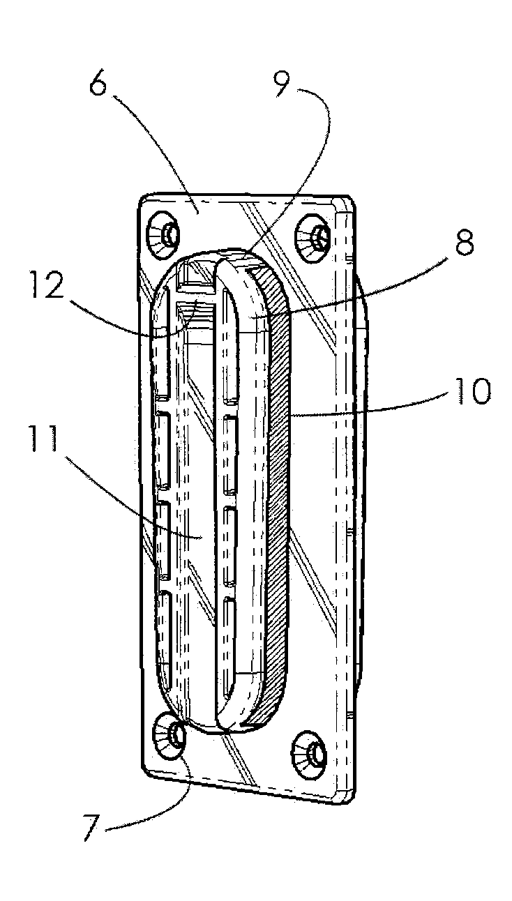
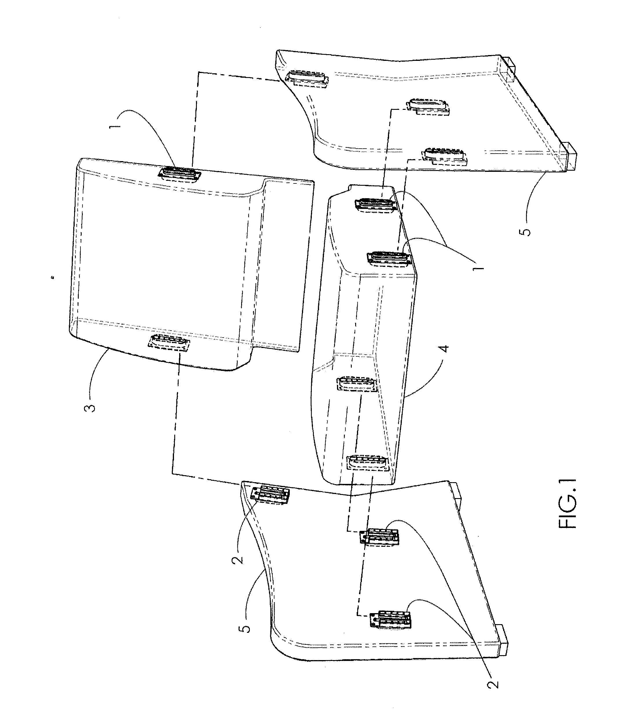
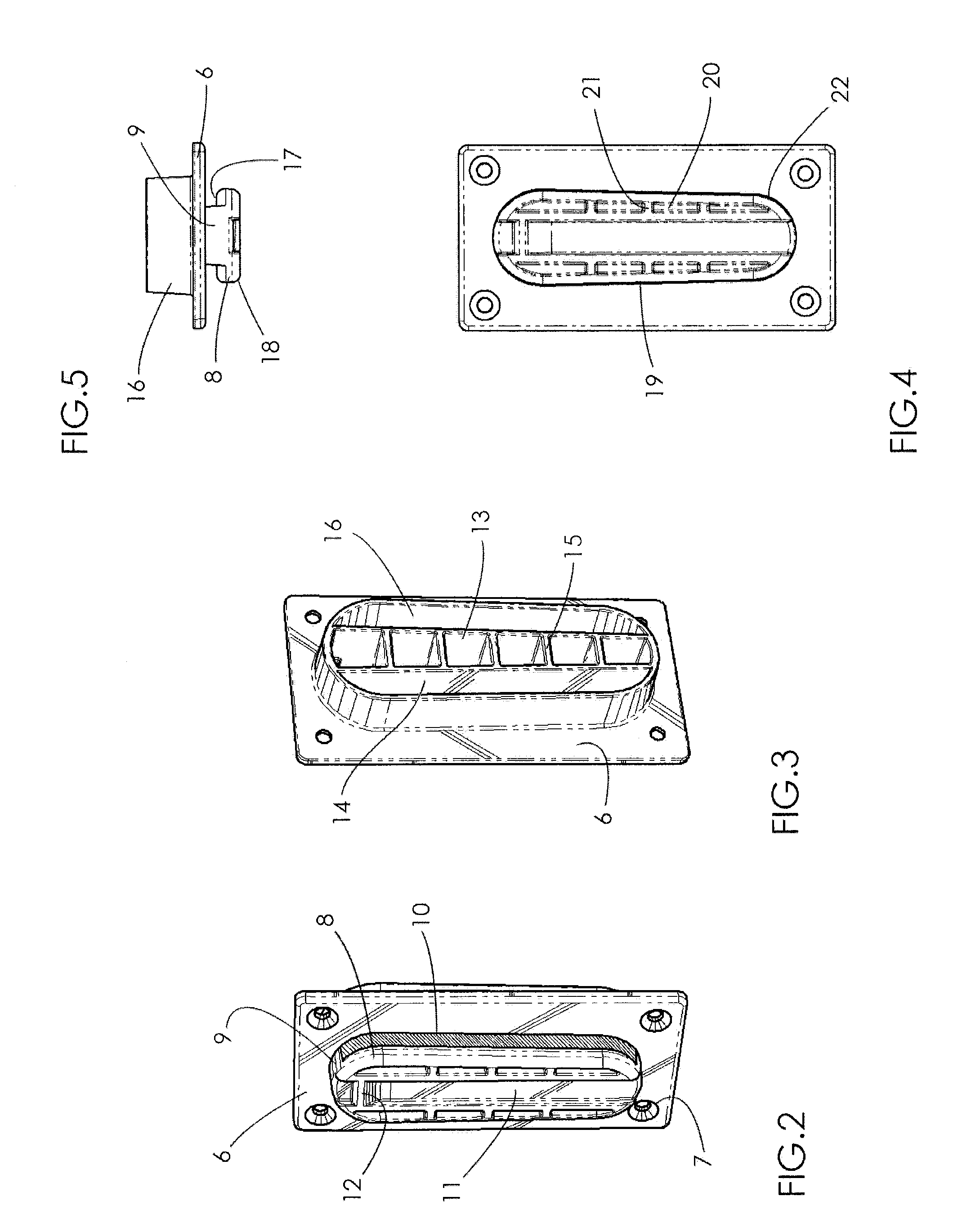
[0032]Referring to the drawings and, in particular to FIG. 1, there is illustrated one embodiment of the invention in which four frame components of an item of furniture, namely the back 3, seat 4, and sides 5 of a chair, that is secured together using the connectors of the present invention. Referring to FIGS. 2-15 each connector comprises first and second interlocking members that are structured to matingly engage one another. Referring to FIGS. 2, 3, 4 and 5, the first connector includes a base plate 6 with a relatively uniform wall thickness that includes four holes 7 through the face of the plate, one at each corner, for attaching the first interlocking member of the connector to the surface of a frame member with mechanical fasteners during the initial assembly process. The base plate 6 can be rounded on all four corners and all exposed edges to prevent tearing of the upholstery fabric during the assembly process. The four holes 7 can include a recessed countersink or counter ...


PUM


Abstract

A connector is provided having a first interlocking member, a second interlocking member, and wherein the second interlocking member is structured to matingly engage the first interlocking member in a female/male connection.

Description

FIELD OF THE INVENTION[0001]The present invention relates to a mechanical connector and, more particularly, to a mechanical connector for furniture.BACKGROUND OF THE INVENTION[0002]Large furniture pieces like club chairs, sofas, loveseats and such can benefit greatly from the ability to ship the furniture piece partially unassembled to allow the separated components to be nested tightly together and to ship in a much smaller carton than if it is assembled. There would be substantial cost savings in being able to ship almost twice as many units of furniture in a standard shipping container, both in shipping and in storage costs. Another advantage for single chairs would be the use of a smaller carton having the ability, over fully assembled pieces, to ship whole units by standard rate bulk-shipping methods at a much lower cost. This would be especially desirable to furniture retailers who are selling furniture primarily through catalogs or internet sites and are regularly shipping fu...

Claims


Application Information

Patent Timeline
IPC IPC(8): F16D1/00B23P11/00
CPCA47C4/02F16B12/125Y10T29/49826Y10S403/11Y10T403/74F16B12/20Y10T403/61A47C4/028
Inventor SAUL, GREGORY M
Owner SAUL GREGORY M
Why Eureka
Try Eureka