Vertical axis windmill

a windmill and vertical axis technology, applied in the direction of machines/engines, renewable energy generation, greenhouse gas reduction, etc., to achieve the effect of convenient use, trouble-free operation and simple construction

Inactive Publication Date: 2010-10-07
TUTT NICHOLAS
View PDF5 Cites 10 Cited by
  • Summary
  • Abstract
  • Description
  • Claims
  • Application Information

AI Technical Summary

Benefits of technology

[0011]A final object of this invention to be specifically enumerated herein is to provide a vertical axis windmill in accordance with the preceding objects and which will conform to conve

Problems solved by technology

However, most of these previously known forms of vertical axis windmills include complex controls for wind-shielding portions thereof whi

Method used


Image

  • Vertical axis windmill
  • Vertical axis windmill
  • Vertical axis windmill

Examples


Embodiment Construction

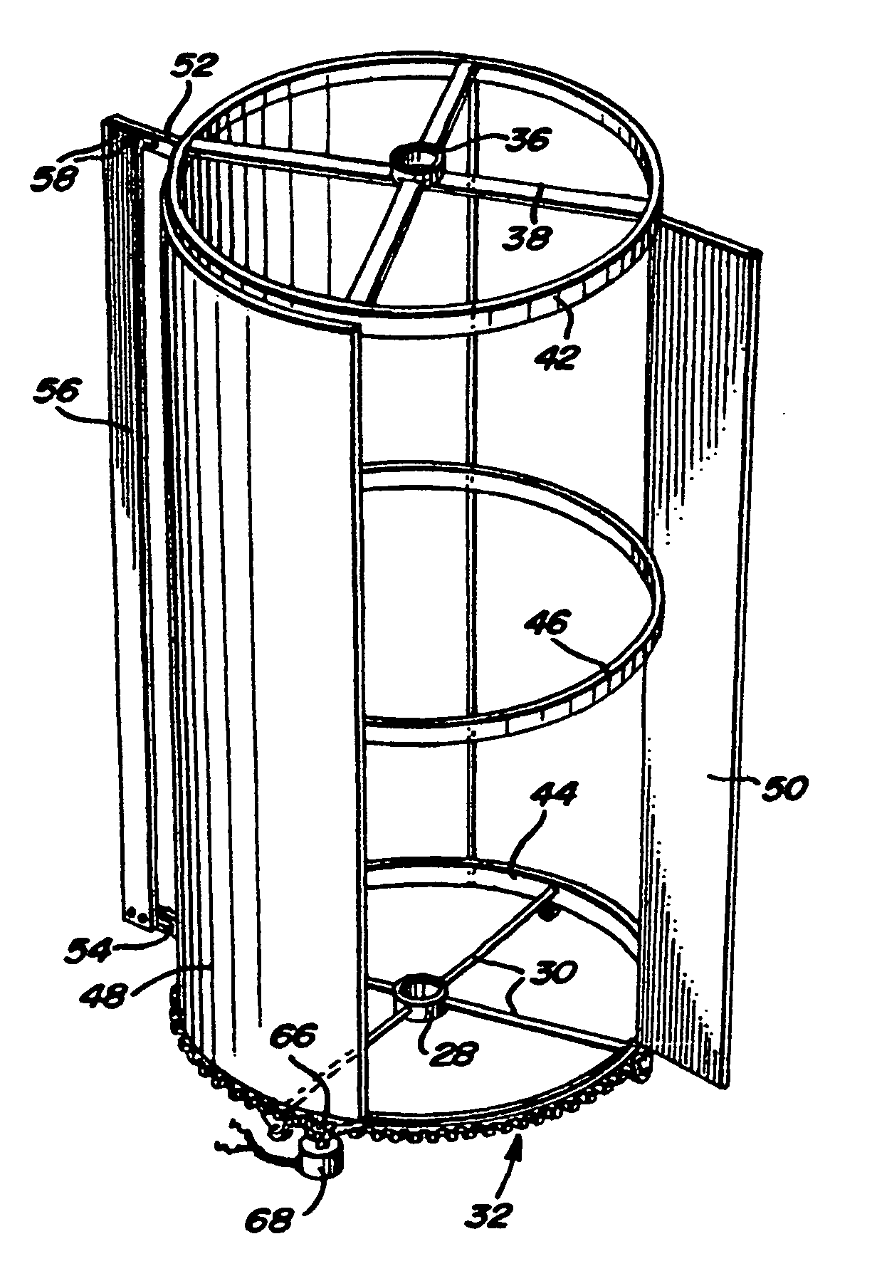
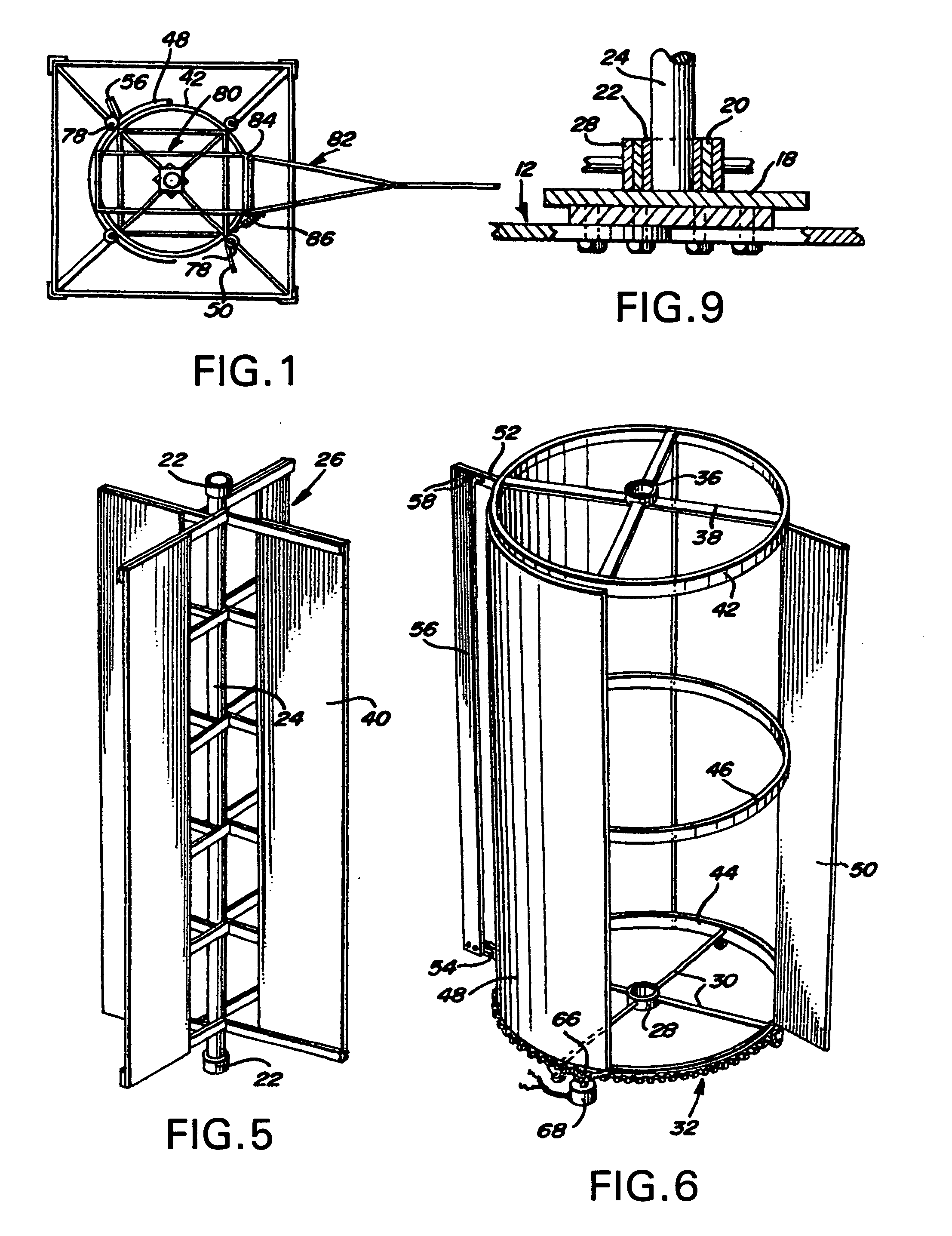
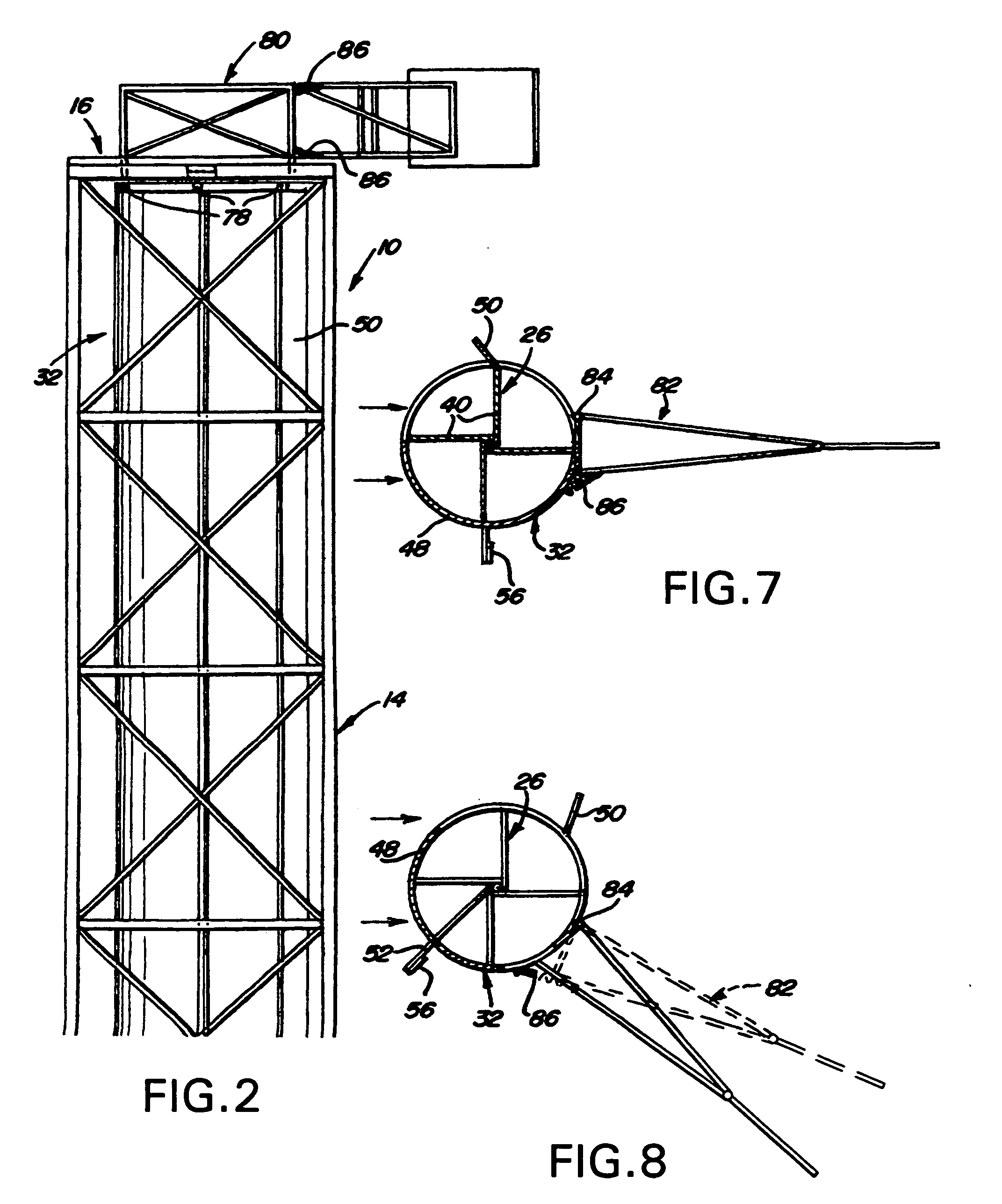
[0027]Referring now more specifically to the drawings the numeral 10 generally designates the vertical axis windmill of the instant invention. The windmill 10 includes a lower base frame assembly referred to in general by the reference numeral 12 and an upright tubular or angle iron support framework referred to in general by the reference numeral 14 supported from the base frame assembly 12. In addition, the upper end of the framework 14 supports an upper frame assembly referred to in general by the reference numeral 16.

[0028]The base frame assembly 12 includes a central portion 18 from which an upstanding cylindrical bearing journal 20 is supported. A sleeve bearing 22 carried by the lower end of the central shaft 24 of a rotor assembly referred to in general by the reference numeral 26 is journalled by the sleeve bearing 22 from the bearing journal 20 and the bearing journal 20 also rotatably journals a cylindrical hub 28 supported by radial arms 30 from the lower end of a windsh...


PUM


Abstract

An upstanding bladed rotor is journalled from support structure and a windshield assembly is also journalled from the support structure for angular displacement about an upstanding axis about the rotor. The windshield assembly includes a wind-shielding portion which extends generally about one half the periphery of the rotor and further includes a wind vane operative to maintain the assembly in predetermined position relative to wind incident upon the rotor with the wind-shielding portion in position to shield generally one lateral half of the rotor from the incident wind. The windshield assembly additionally includes a combined wind booster and excess wind controlling vane supported therefrom and disposed outward of the other lateral half of the rotor into the sweep area thereof responsive to high velocity wind incident thereon so as to apply rotary torque to the windshield assembly partially overcoming the directional control thereon by the wind vane and swinging the wind-shielding portion into position across the side of the rotor upon which the wind is incident so as to reduce the amount of high velocity wind available to drive the rotor and thus prevent the latter from overspeeding.

Description

CROSS REFERENCE TO RELATED APPLICATIONS[0001]This application claims benefit of U.S. Provisional Patent Application Ser. No. 61 / 210,728, filed on Mar. 23, 2009.BACKGROUND OF THE INVENTION[0002]Various different forms of vertical windmills heretofore have been designed and provided with wind-shielding structure and other features such as those included on the windmill of the instant invention. Examples of these previously known forms of vertical axis windmills are disclosed in U.S. Pat. Nos. 204,404, 1,096,057, 1,640,296, 1,687,181, 1,974,008, 4,031,405, 4,134,707, 4,237,384, 4,245,958 and 4,278,896.[0003]However, most of these previously known forms of vertical axis windmills include complex controls for wind-shielding portions thereof which do not perform the dual function of wind-shielding at high wind velocities as well as wind flow concentrating at lower wind velocities.[0004]Accordingly, a need exists for a simplified vertical axis windmill with automatic wind-shielding structu...

Claims


Application Information

Patent Timeline
IPC IPC(8): F03D7/06
CPCY02E10/74F03D3/0436Y10S415/907F03D80/70F03D3/0472
Inventor TUTT, NICHOLAS
Owner TUTT NICHOLAS
Why Eureka
Try Eureka