Pouch type secondary battery with improved safety

a secondary battery and pouch-type technology, applied in the direction of cell sealing materials, cell components, cell cases/jackets, etc., can solve the problems of pouch-type secondary batteries being susceptible to internal short circuit risk, lithium secondary batteries may undergo explosion, and no sealing in the inside portions, so as to facilitate the design of safer battery packs and safety devices, the effect of improving safety

Active Publication Date: 2010-10-07
LG ENERGY SOLUTION LTD
View PDF4 Cites 21 Cited by
  • Summary
  • Abstract
  • Description
  • Claims
  • Application Information

AI Technical Summary

Benefits of technology

[0016]As will be described in name detail hereinafter, a pouch-type secondary battery of the present invention is configured in a manner that when gases evolve inside the battery, unidirectional discharge of gases is allowed through the formation of a channel using sealing portions of electrode tabs. Therefore, it is possible to easily design a safer battery pack and safety device. Further, the present invention provides a pouch type secondary battery with improved safety, because discharge of gases is name easily achieved when the inside of the battery reaches a certain level of pressure.

Problems solved by technology

Generally, the lithium secondary battery may undergo explosion of the battery die to high internal temperature and pressure thereof which may result from abnormal operation conditions of the battery, such as internal short circuit, excessive charged state over an acceptable level of electric current and voltage, exposure of the battery to high temperatures, and external impact such as falling.
For example, the pouch-type secondary battery is susceptible to the risk of an internal short circuit when it is exposed to external impact such as falling or application of force from the outside.
Unfortunately in this case, substantially no sealing is achieved in inside portions 30,30′ of the electrode tabs, so adhesive strength is weak in the region (as indicated by the circle) where the electrode tabs 10,10′ and sealing portions are not overlapped with each other.
As a consequence, there is a high possibility of gas discharge toward the region which will have poor adhesive strength upon sealing of the external pouch structure and the electrode tabs.
Such an undesirable event takes place in the configuration of FIG. 2 where the electrode tabs are installed parallel to each other on either side of the battery as well as in the configuration of FIG. 1 where the electrode tabs are installed on both top and bottom sides of the battery.
In such a case, discharge of gases takes place in unexpected regions (as indicated by the circle), which may result in difficulties associated with a design of a battery pack for HEVs.
Multidirectional venting of gases from the inside of the battery pack, not unidirectional venting of gases, does not allow easy discharge of gases to the outside.
Further, although discharge of internal gases should be achieved more quickly to secure safety of the battery upon evolution of gases inside the battery, a conventional battery is highly vulnerable to significant deterioration of the battery safety due to an extended period of time required for venting gases.

Method used


Image

  • Pouch type secondary battery with improved safety
  • Pouch type secondary battery with improved safety
  • Pouch type secondary battery with improved safety

Examples


example 1

Fabrication of a Secondary Battery Having Second Sealing Portions in a Structure including Electrode Tabs Formed on Both Sides of the Battery

[0043]A negative electrode tab of a 0.3 mm-thick copper was prepared which is attached to a negative collector of an electrode assembly consisting of a negative electrode / separator / positive electrode. Then, aluminum foil (for a positive electrode lead) and copper foil (for a negative electrode lead) were respectively welding-attached to the corresponding electrode tabs. Next, as shown in FIGS. 5 and 6, a secondary battery with formation of second sealing portions (250±20 μm) was fabricated with modification of a sealing tool. The electrode assembly was placed in a pouch-type case made of an aluminum laminate sheet, and a carbonate-based lithium electrolyte containing 1M LiPF6 was then injected thereto, followed by thermal fusion of the sheet to fabricate a lithium ion polymer battery.

example 2

Fabrication of a Secondary Battery Having Second Sealing Portions in a Structure including Electrode Tabs Formed on Either Side of the Battery

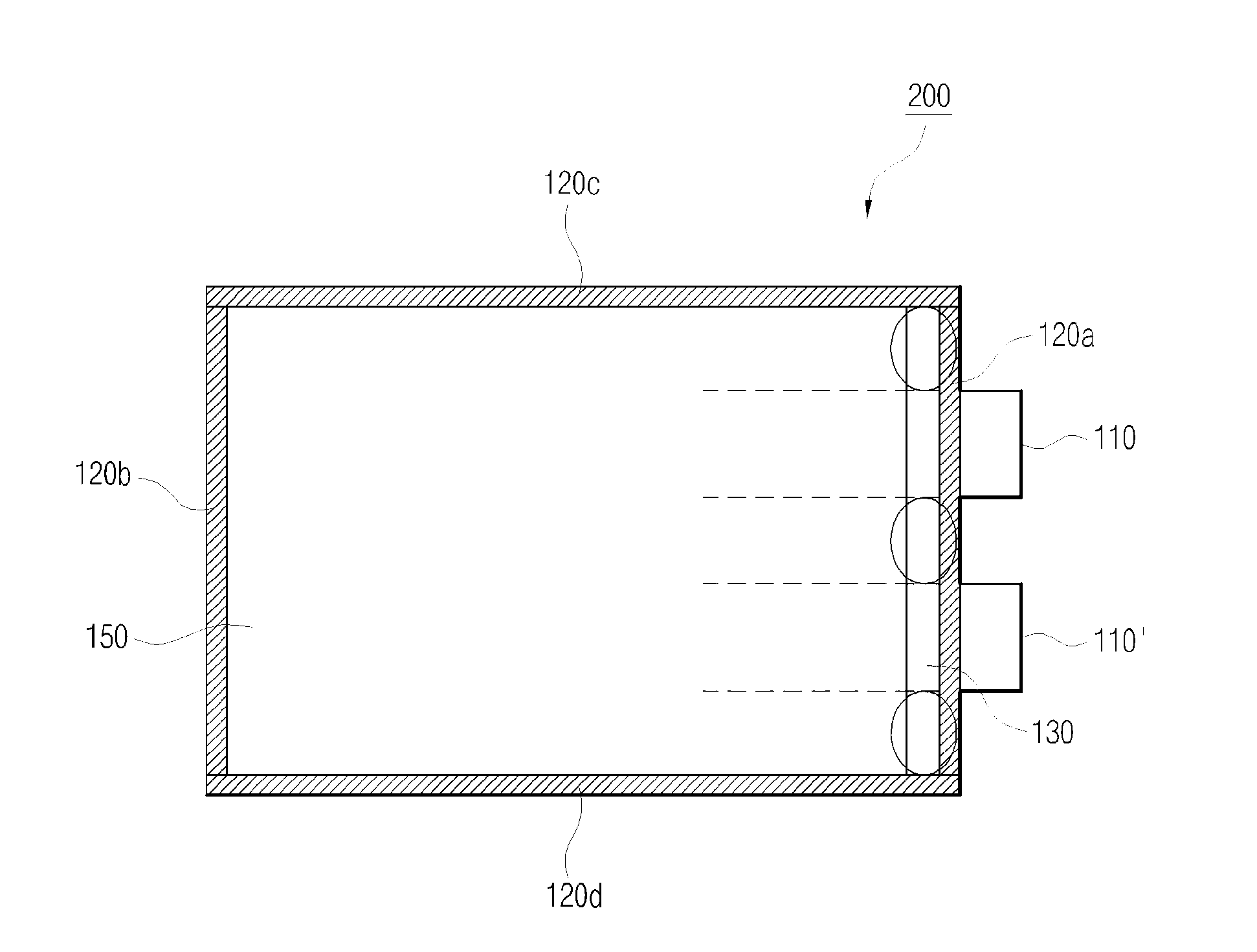
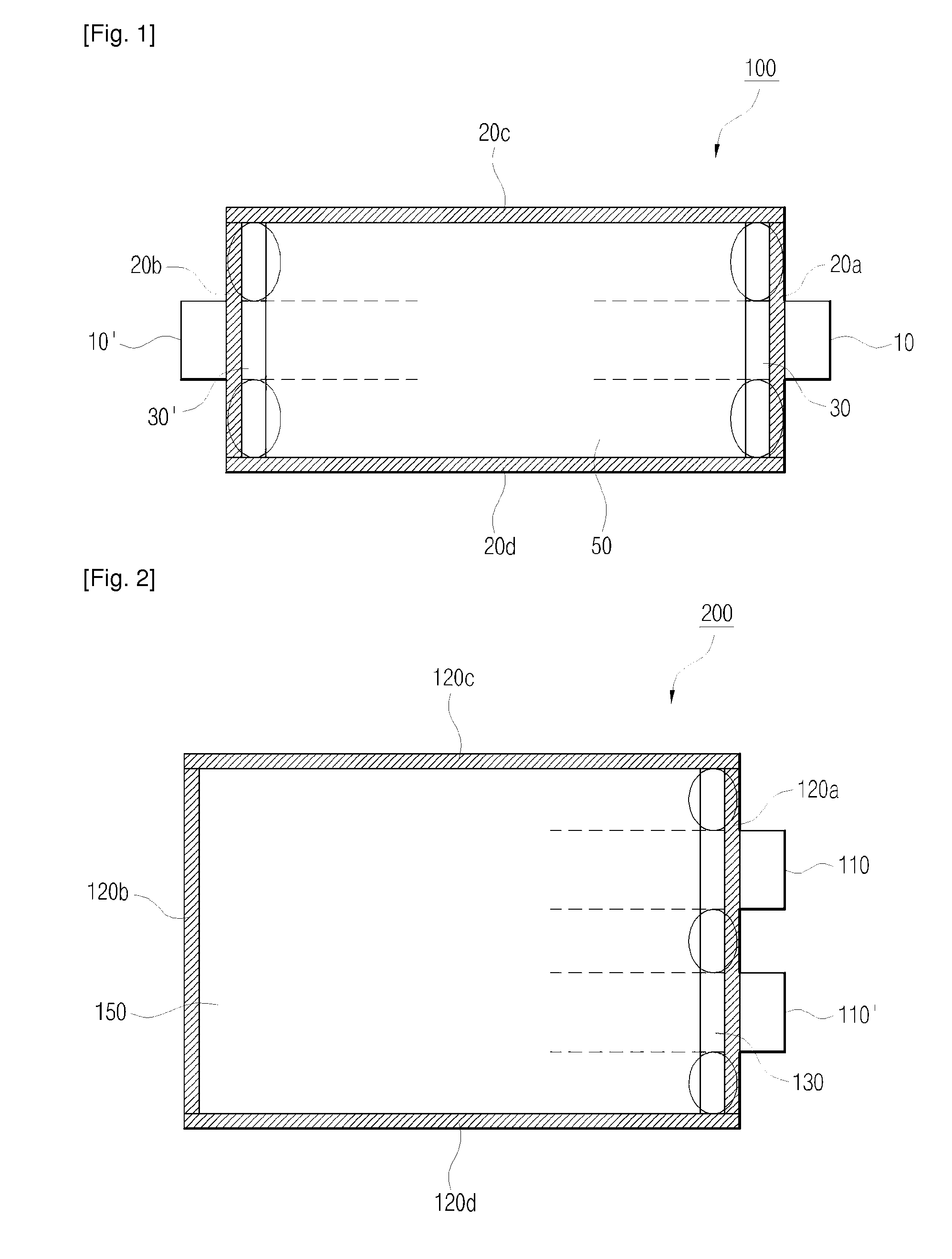
[0044]A lithium ion polymer battery was fabricated in the same manner as in Example 1, except that second sealing portions (250±20 μm) were formed with modification of a sealing tool, as shown in FIG. 7.

experimental example 1

[0046]Safety of the secondary batteries fabricated in Examples 1 and 2 and Comparative Example 1 was measured. The results thus obtained are given in Table 1 below.

TABLE 1Comparative Example 1Examples 1 and 2Vent directionVenting of gases atVenting of gases tosides of cellelectrode tabs

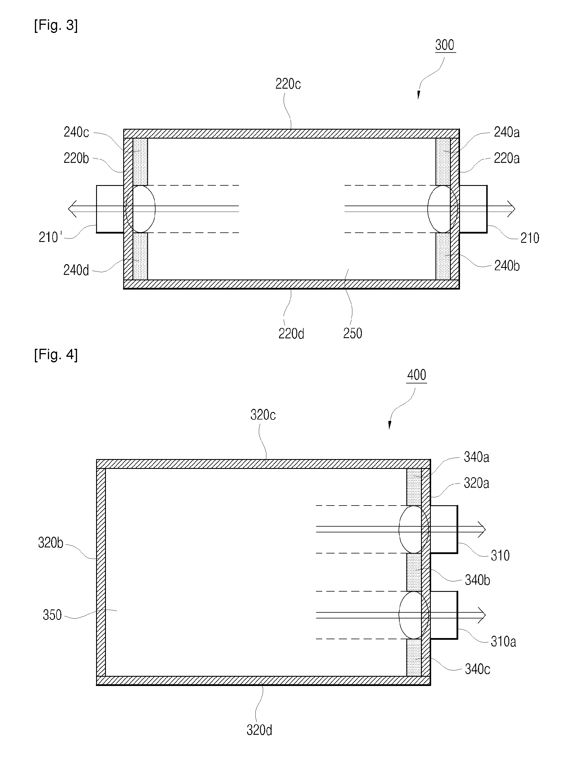
[0047]From the results of Table 1, it can be seen that formation of second sealing portions as in the present invention resulted in venting of gases to the electrode tabs, whereas no installation of second sealing portions as in Comparative Example 1 resulted in venting of gases in the non-uniform direction and toward a weak sealing part.


PUM

PropertyMeasurementUnit
thicknessaaaaaaaaaa
thicknessaaaaaaaaaa
thicknessaaaaaaaaaa

Abstract

Provided is a pouch-type secondary battery including an electrode assembly, electrode tabs extending outward from the electrode assembly, a pouch-type battery case for housing the electrode assembly, first sealing portions for sealing the pouch-type battery case and the electrode tabs, and second sealing portions formed at positions with the exception of electrode tab-positioned sites between the first sealing portions and the electrode assembly. The secondary battery is configured to have a structure such that a channel is formed with electrode tab portions by further sealing inside portions of the electrode tabs with the exception of electrode tab-occupied portions. Such a structure allows for easy unidirectional discharge of gases even when the battery inside reaches a certain level of internal pressure due to evolution of gases and enables previous expectation of the gas discharge direction. Therefore, it is possible to provide a secondary battery with improved safety.

Description

TECHNICAL FIELD[0001]The present invention relates to a pouch type secondary battery with improved safety. More specifically, the present invention relates to a pouch type secondary battery which is capable of achieving improved safety by sealing a non-overlapped portion between an electrode tab and a pouch to make a channel between a battery cell and a tab-sealing portion, such that gases generated from the inside of the battery can be discharged only in the direction of the electrode tab.BACKGROUND ART[0002]Technological development and increased demand for mobile equipment have led to a rapid increase in the demand for secondary batteries as an energy source. To keep with such current trends, a great deal of research and stilly has been focused on development of batteries that can meet various requirements of consumers.[0003]In terms of the battery shape, there is a great demand for rectangular batteries and pouch-type batteries which have a slim thickness and are therefore appli...

Claims


Application Information

Patent Timeline
Patent Type & Authority Applications(United States)
IPC IPC(8): H01M2/08H01M50/548H01M50/55H01M50/557
CPCH01M2/0212H01M2/0217H01M2/0287H01M10/0565H01M2/1241H01M10/0525H01M2/08Y02E60/10H01M50/557H01M50/103H01M50/124H01M50/3425H01M50/55H01M50/548
Inventor PARK, HYUN WOOYOO, KWANG HOSHIN, YOUNG JOONLEE, HAN HO
Owner LG ENERGY SOLUTION LTD
Why Eureka
Try Eureka