
Standalone system for assisting in a life-saving situation

a life-saving situation and stand-alone technology, applied in the field of stand-alone systems for life-saving situations, can solve the problems of not considering ventilation, ventilation inactivity or compression inactivity, and no prior art systems or devices that provide feedback, so as to achieve better treatment and increase the chance of survival

Active Publication Date: 2010-10-07
LAERDAL MEDICAL AS
View PDF8 Cites 37 Cited by
  • Summary
  • Abstract
  • Description
  • Claims
  • Application Information

AI Technical Summary

Benefits of technology

[0014]A further object of the invention is to provide a device for providing feedback to the rescuer in order to improve the CPR treatment, the device being small, versatile, dependable and affordable.
[0017]The feedback is in one embodiment provided by indications to the rescuer by means of tactile feedback to the rescuer's hand provided in an energy efficient way, e.g., to prolong battery life and thus the dependability of the device when stored without charging.

Problems solved by technology

Recent publications have pointed out numerous problems with how CPR is being conducted today by professionals.
This device does not consider ventilation, ventilation inactivity or compression inactivity.
Acquiring a new defibrillator with a CPR assist device might not be an option for Emergency Medical Systems (EMS) which already has a well functioning AED / Defibrillator system.
There are no prior art systems or devices that provide feedback on both compression and ventilation activity as well as on inactivity through the full procedure of CPR.
Another problem related to known systems, such as for example the AEDplus from Zoll, is that they are relatively expensive, big, and complicated; so that lay rescuers will not keep them available at all times. Devices made for lay rescuers are described in EP1578340, which describes force sensitive devices giving sound signals for assisting the rescuer, and, more particularly, a device for placement between the hands of a person performing chest compression and the chest of a patient.
Practice has shown that sound signals in some cases may be difficult to hear, especially in some emergency situations.
If, for example, the applied force is too strong, there is a risk of hurting the patient.

Method used


Image

  • Standalone system for assisting in a life-saving situation
  • Standalone system for assisting in a life-saving situation
  • Standalone system for assisting in a life-saving situation

Examples


Embodiment Construction

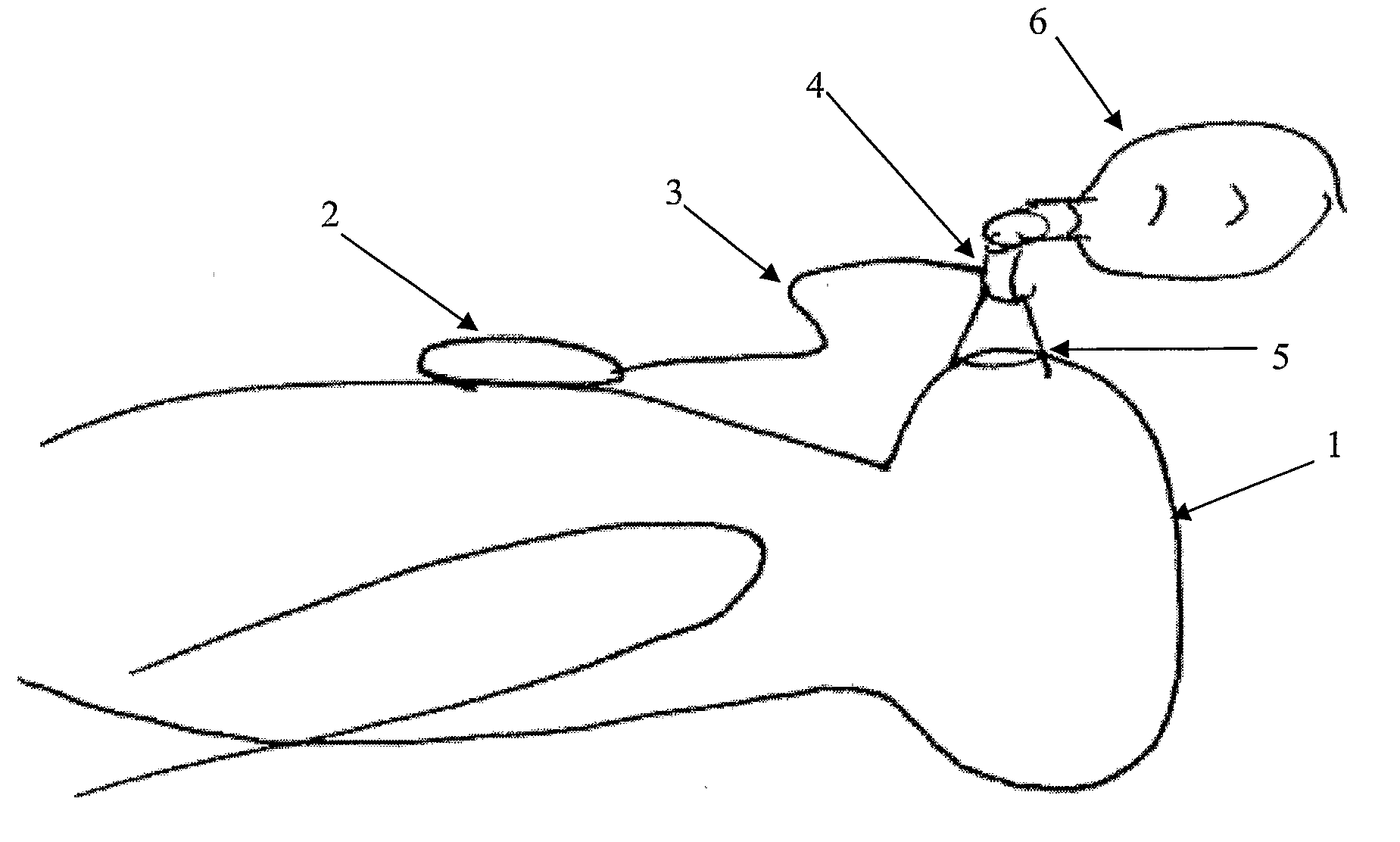
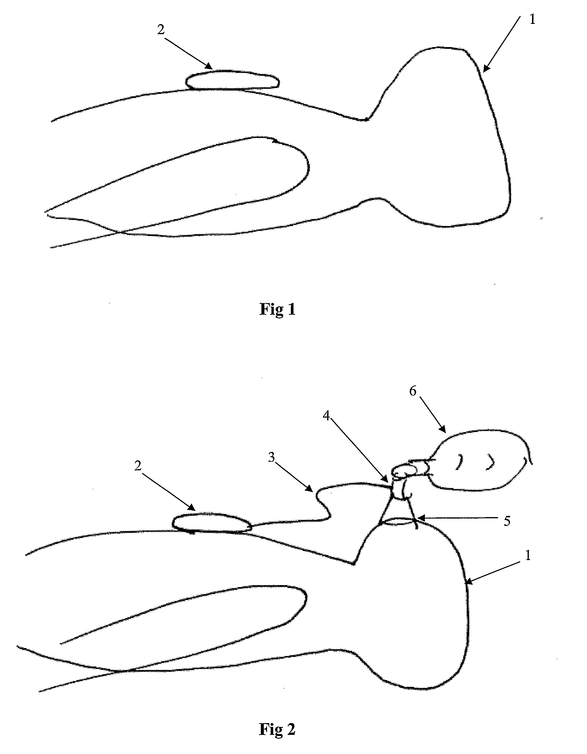
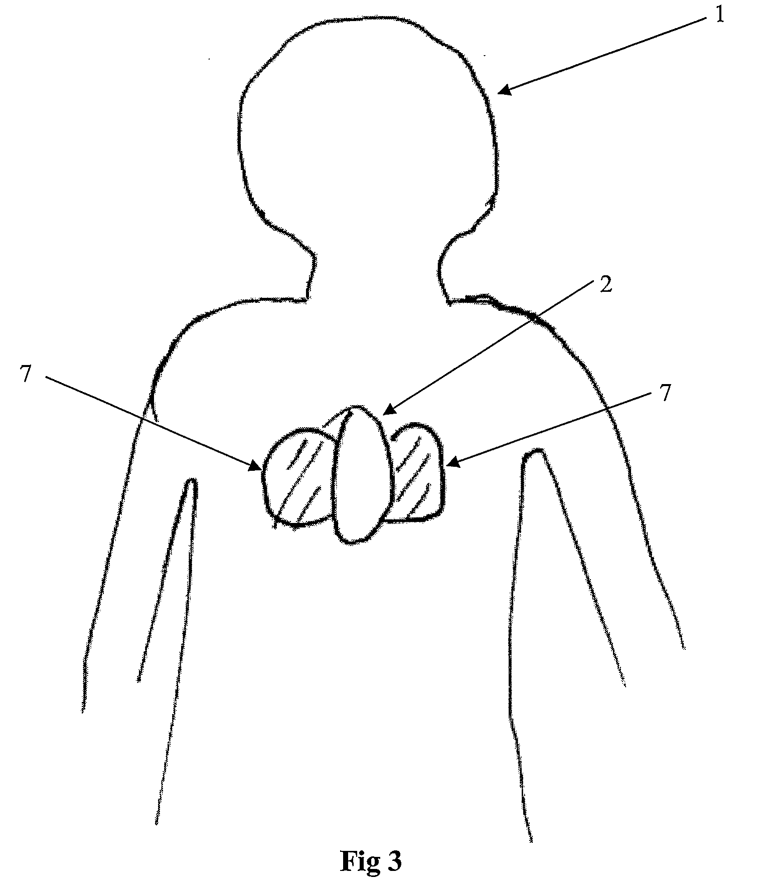
[0059]FIG. 1 shows a patient 1 with a compression unit 2 attached to his / her chest. The unit 2 may be attached using adhesive tape. When a rescuer performs compressions on the patient's chest, the rescuer places his hand on top of the unit 2. The unit 2 will therefore travel the same distance as the chest is compressed. A movement sensor, including or connected to a calculation means, located inside the compression unit will detect the distance / depth. The movement sensor may be an accelerometer, but other solutions may be employed such as use of a gyro or distance measurements from a reference point or by triangulation. In case of an accelerometer, in order to find the depth, the signal from the sensor will have to be filtered and double-integrated, as is well know in the art. An additional force sensitive unit, in its most simple form just a force activated switch, will also be part of the unit. This force sensitive unit will be activated each time the rescuer performs a compressio...


PUM


Abstract

A system and a method is disclosed for monitoring parameters during cardiopulmonary resuscitation, including a compression measuring means, a ventilation measuring means and a processing means. If at least one of the measured values deviate from a respective reference range, the processing means provides an indication of the deviation. If more than one of the measured values deviate from a respective reference range, the deviations are prioritized with an indication being provided first to the deviation having a higher priority. The invention also regards a device for positioning on a patient's chest during cardiopulmonary resuscitation, which measures compression and which comprises a feedback module for providing a tactile output related to the measurements.

Description

CROSS-REFERENCE TO RELATED APPLICATIONS[0001]This application is a national phase application of International Patent Application Serial No. PCT / NO2006 / 000061, filed Feb. 15, 2006, which application claims priority to U.S. Provisional Patent Application Ser. No. 60 / 752,041, filed Dec. 21, 2005, and to United Kingdom Patent Application Serial No. 0550383.4, filed Feb. 24, 2005, and to Norwegian Patent Application Serial No. 20050798, filed Feb. 15, 2005, all of which are hereby incorporated by reference.TECHNICAL FIELD[0002]This invention relates to a systems and devices designed to measure, record and provide feedback on the performance of cardiopulmonary resuscitation (CPR) as applied to victims of cardiac arrest or a manikin used for training purposes.BACKGROUND OF THE INVENTION[0003]Cardiopulmonary resuscitation (CPR) is a procedure performed as life-saving first aid in cases of a sudden cardiac arrest. The procedure comprises performing chest compressions and ventilation. Recent...

Claims


Application Information

Patent Timeline
IPC IPC(8): A61H31/00A61B5/113
CPCA61B5/0816A61M16/0084A61H31/005A61H31/006A61H31/007A61H2201/5071A61H2201/5084A61H2230/40A61H2230/42A61H2230/65A61M15/0086A61M16/0078A61M2016/0027A61M2016/0036A61M2205/581A61M2205/582A61M2205/583A61M2230/432A61M2230/50A61M2230/63A61M2230/65A61B5/091A61B5/7455
Inventor STRAND, GEIRFOSSAN, HELGEMORALLEE, KENNETH GEORGEMYKLEBUST, HELGEKNUTSEN, RUNE KRISTIAN
Owner LAERDAL MEDICAL AS
Learn More