
Exhaust purification system of internal combustion engine

a technology of exhaust purification system and internal combustion engine, which is applied in the direction of machine/engine, exhaust treatment electric control, separation process, etc., can solve the problems of insufficient storage of nox storage/reduction catalyst device, difficult to release sox, and increase in difficulty

Inactive Publication Date: 2010-10-14
TOYOTA JIDOSHA KK
View PDF7 Cites 8 Cited by
  • Summary
  • Abstract
  • Description
  • Claims
  • Application Information

AI Technical Summary

Benefits of technology

[0006]To prevent heat deterioration of the NOx storage / reduction catalyst device, SOx should not be stored in the NOx storage / reduction catalyst device. Accordingly, an S trap device for storing SOx similarly with the NOx storage / reduction catalyst device may be arranged upstream of the NOx storage / reduction catalyst device.
[0008]Accordingly, an object of the present invention is to provide an exhaust purification system of an internal combustion engine in which a particulate filter is arranged downstream of an NOx storage / reduction catalyst device and an S trap device is arranged upstream of the NOx storage / reduction catalyst device, which can prevent SOx from being released from the S trap device when a part of the additional fuel supplied to the exhaust system upstream of the S trap device or into the cylinder gas is burned in the NOx storage / reduction catalyst device to increase the temperature of the exhaust gas flowing into the particulate filter and a good regeneration treatment of the particulate filter is carried out.
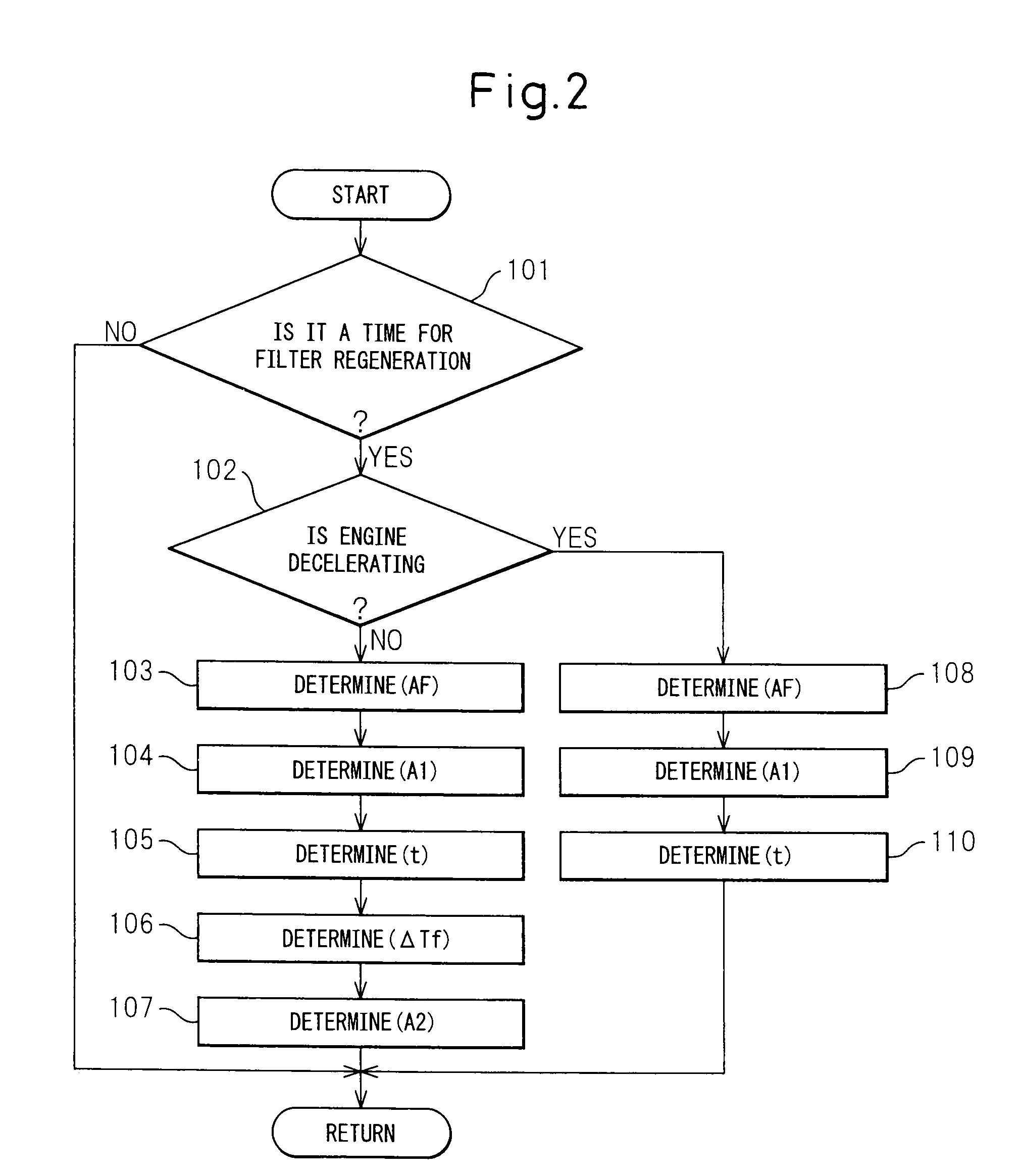
[0012]According to the exhaust purification system of the internal combustion engine as set forth in claim 1 of the present invention, the additional fuel for the regeneration treatment of the particulate filter is supplied to the exhaust system upstream of the S trap device or into the cylinder by the first fuel supplying means. An amount of the additional fuel supplied by the first fuel supplying means is controlled to make the S trap device not release SOx and thus the S trap device is prevented from releasing SOx. A part of the additional fuel supplied by the first fuel supplying means is burned in the NOx storage / reduction catalyst device to increase the temperature of the exhaust gas flowing into the particulate filter, and therefore the remaining additional fuel can be burned in the particulate filter to further increase the temperature of the particulate filter. However, the amount of the additional fuel supplied by the first fuel supplying means cannot sufficiently increase the temperature of the particulate filter and is in short supply for the regeneration treatment of the particulate filter. Accordingly, the second fuel supplying means is provided in the exhaust system between the NOx storage / reduction catalyst device and the particulate filter, and the second fuel supplying means can make up for a deficiency of the additional fuel supplied by the first fuel supplying means. Thus, the temperature of the particulate filter can be increased at the desired temperature to realize good regeneration treatment of the particulate filter.

Problems solved by technology

Because, SOx is stored as a stable sulfate, it is difficult to release SOx.
Therefore, an amount of SOx stored in the NOx storage / reduction catalyst device goes on increasing and finally the NOx storage / reduction catalyst device comes to insufficiently store NOx.

Method used


Image

  • Exhaust purification system of internal combustion engine
  • Exhaust purification system of internal combustion engine
  • Exhaust purification system of internal combustion engine

Examples


Embodiment Construction

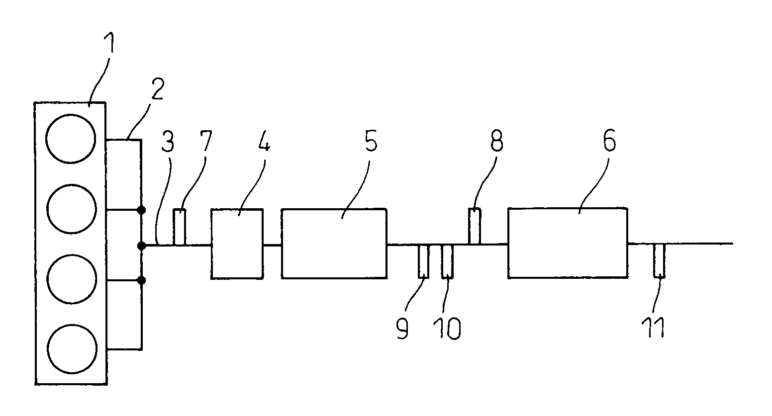
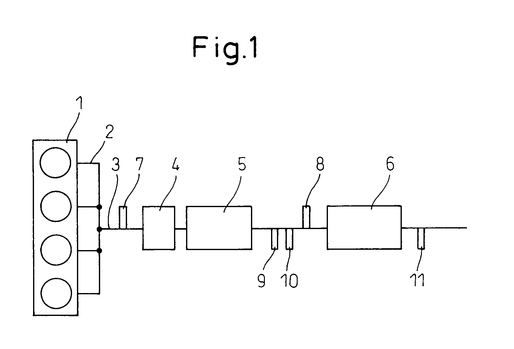
[0019]FIG. 1 is a schematic view showing an embodiment of an exhaust purification system of an internal combustion engine according to the present invention. In FIG. 1, reference numeral 1 is an engine body performing lean combustion such as a diesel engine. Reference numeral 2 is an exhaust manifold. Reference numeral 3 is an exhaust passage downstream of the exhaust manifold 2. In the exhaust passage 3, an S trap device 4, an NOx storage / reduction catalyst device 5 downstream of the S trap device 4, and a particulate filter 6 downstream of the NOx storage / reduction catalyst device 5 are arranged.

[0020]In such an arrangement, SOx in the exhaust gas is stored in the S trap device 4 upstream of the NOx storage / reduction catalyst device and is not almost stored in the NOx storage / reduction catalyst device 5. Therefore, the NOx storage / reduction catalyst device 5 is not required to release SOx with heat deterioration. The S trap device 4 is exchanged with a new one (or one which is abl...


PUM

PropertyMeasurementUnit
concentrationaaaaaaaaaa
exhaust resistanceaaaaaaaaaa
temperatureaaaaaaaaaa

Abstract

In the present exhaust purification system of an internal combustion engine, a particulate filter is arranged downstream of an NOx storage / reduction catalyst device and an S trap device is arranged upstream of the NOx storage / reduction catalyst device. A first fuel supplying means for supplying additional fuel for regeneration of the particulate filter to the exhaust system upstream of the S trap device or into the cylinder is provided. An amount of the additional fuel supplied by the first fuel supplying means is controlled to make the S trap device not release SOx. A second fuel supplying means is provided in the exhaust system between the NOx storage / reduction catalyst device and the particulate filter to make up for a deficiency of the additional fuel supplied by the first fuel supplying means in the regeneration treatment of the particulate filter.

Description

TECHNICAL FIELD[0001]The present invention relates to an exhaust purification system of an internal combustion engine.BACKGROUND ART[0002]In an exhaust system of an internal combustion engine which performs lean combustion like a diesel engine, a NOx storage / reduction catalyst device is arranged. The NOx storage / reduction catalyst device satisfactorily stores NOx when the air-fuel ratio of the exhaust gas is lean, namely when the concentration of oxygen in the exhaust gas is high. On the other hand, as a regeneration treatment, when the air-fuel ratio of the exhaust gas is made a stoichiometric air-fuel ratio or a rich air-fuel ratio, namely, the concentration of oxygen is decreased, the NOx storage / reduction catalyst device releases the stored NOx and purifies to reduce the released NOx by reducing materials in the exhaust gas.[0003]The exhaust gas of the internal combustion engine also includes particulates. It is desired to trap the particulates and reduce the amount of particula...

Claims


Application Information

Patent Timeline
Patent Type & Authority Applications(United States)
IPC IPC(8): F01N9/00F01N3/035
CPCB01D46/006F01N13/009B01D53/9422B01D53/9477B01D53/949B01D2255/915B01D2257/302B01D2279/30F01N3/0253F01N3/0807F01N3/0814F01N3/085F01N3/0885F01N2250/14F01N2570/04F01N2610/03B01D46/42B01D46/80
Inventor NISHIOKA, HIROMASAHIROTA, SHINYAHAYASHI, KOTAROASANUMA, TAKAMITSUYOSHIDA, KOHEIOTSUKI, HIROSHI
Owner TOYOTA JIDOSHA KK
Learn More