

Exhaust emission control device
- Summary
- Abstract
- Description
- Claims
- Application Information
AI Technical Summary
Benefits of technology
Problems solved by technology
Method used
Image

Examples
Embodiment Construction
[0036]An embodiment of the invention will be described in conjunction with the drawings.
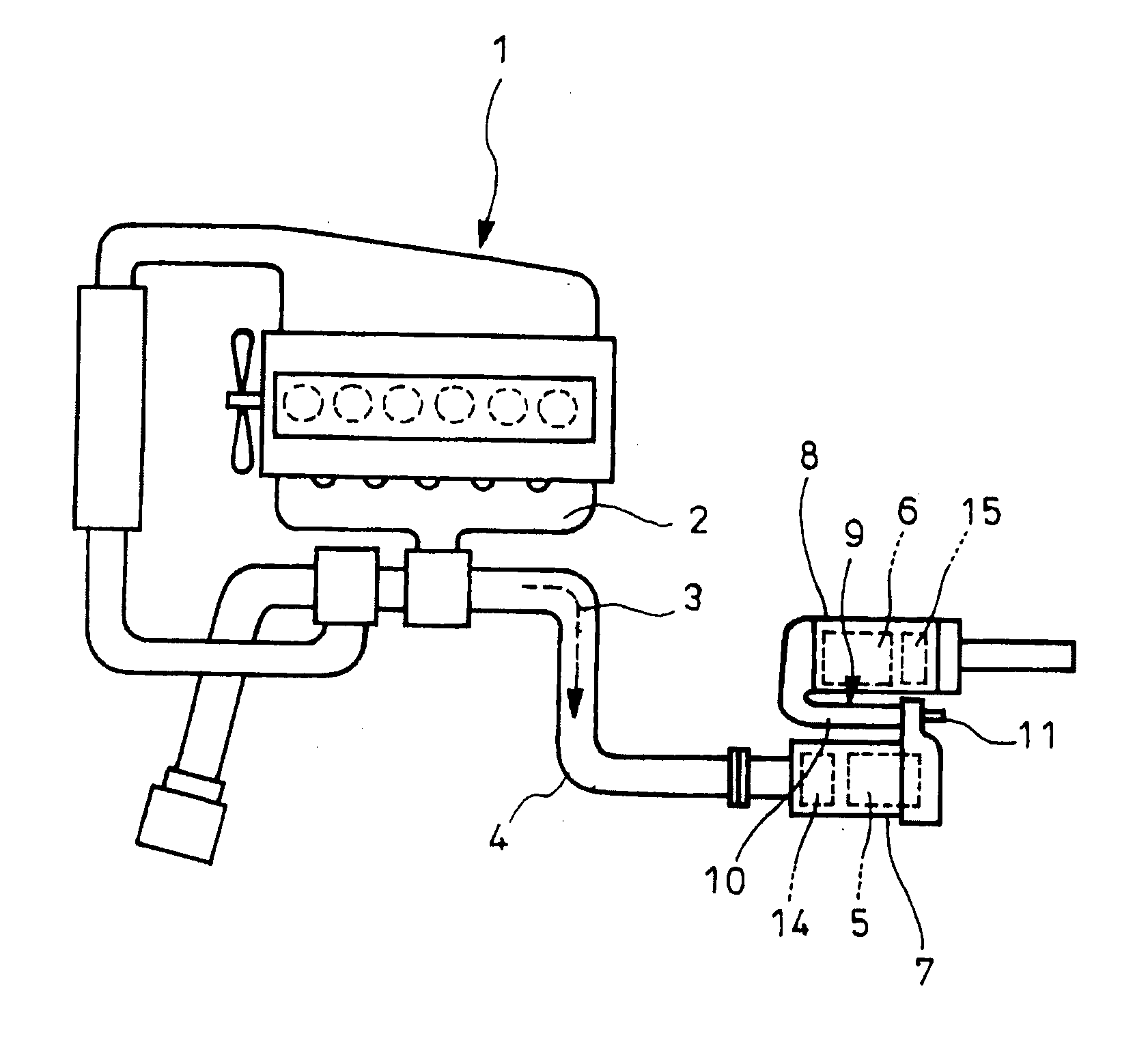
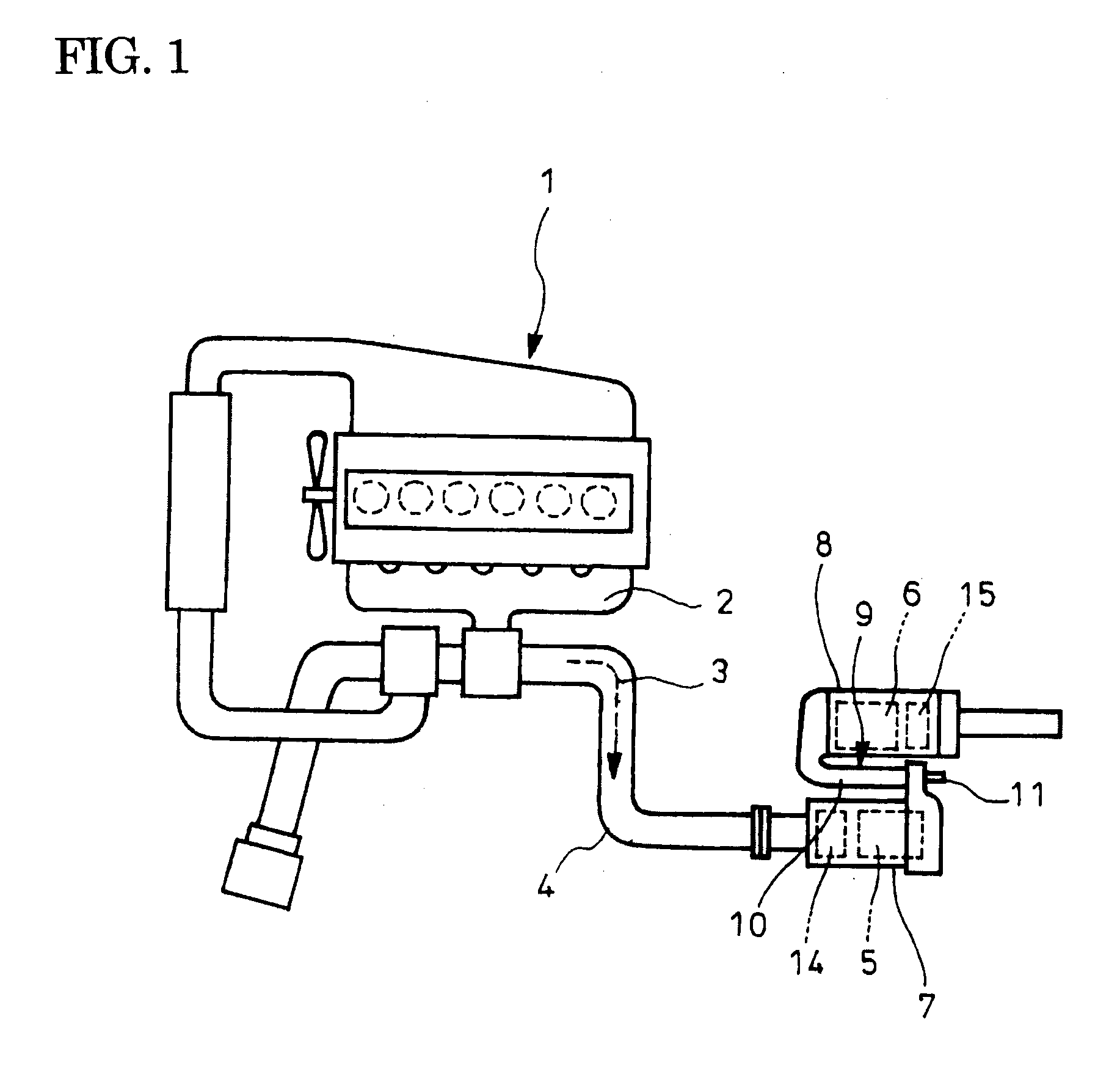
[0037]FIG. 3 shows an embodiment of an exhaust emission control device according to the invention. In the embodiment directed to an exhaust emission control device constructed substantially similar to that described above with reference to FIGS. 1 and 2, an intermediate portion of a mixing pipe 10 (straight portion extending axially of the particulate filter 5 and the selective reduction catalyst 6 (see FIG. 1)) in a communication passage 9 provides a double-wall portion 18 where inner and outer pipes 16 and 17 providing upstream and downstream ducts in the mixing pipe 10, respectively, are overlapped with each other in a relatively stretchable and retractable manner.
[0038]The outer pipe 17 in the double-pipe portion 18 has a terminal end secured to an outer periphery of the inner pipe 16 and is formed at its appropriate portion with an axially expansible and contractible bellows 19. The inner pi...
PUM
 Abstract
Description
Claims
Application Information