Drum winch

Active Publication Date: 2010-10-14
STRESS FREE MARINE
View PDF13 Cites 6 Cited by
  • Summary
  • Abstract
  • Description
  • Claims
  • Application Information

AI Technical Summary

Benefits of technology

[0013]It is envisaged that it would be advantageous to include some means for preventing or at least reducing continued free rotation (i.e. overrun) of the drum when the anchor hits the ocean bottom. To this end some means for ‘braking’ the drum may be i

Problems solved by technology

A disadvantage of such powered anchor drum winches

Method used


Image

  • Drum winch
  • Drum winch
  • Drum winch

Examples


Example

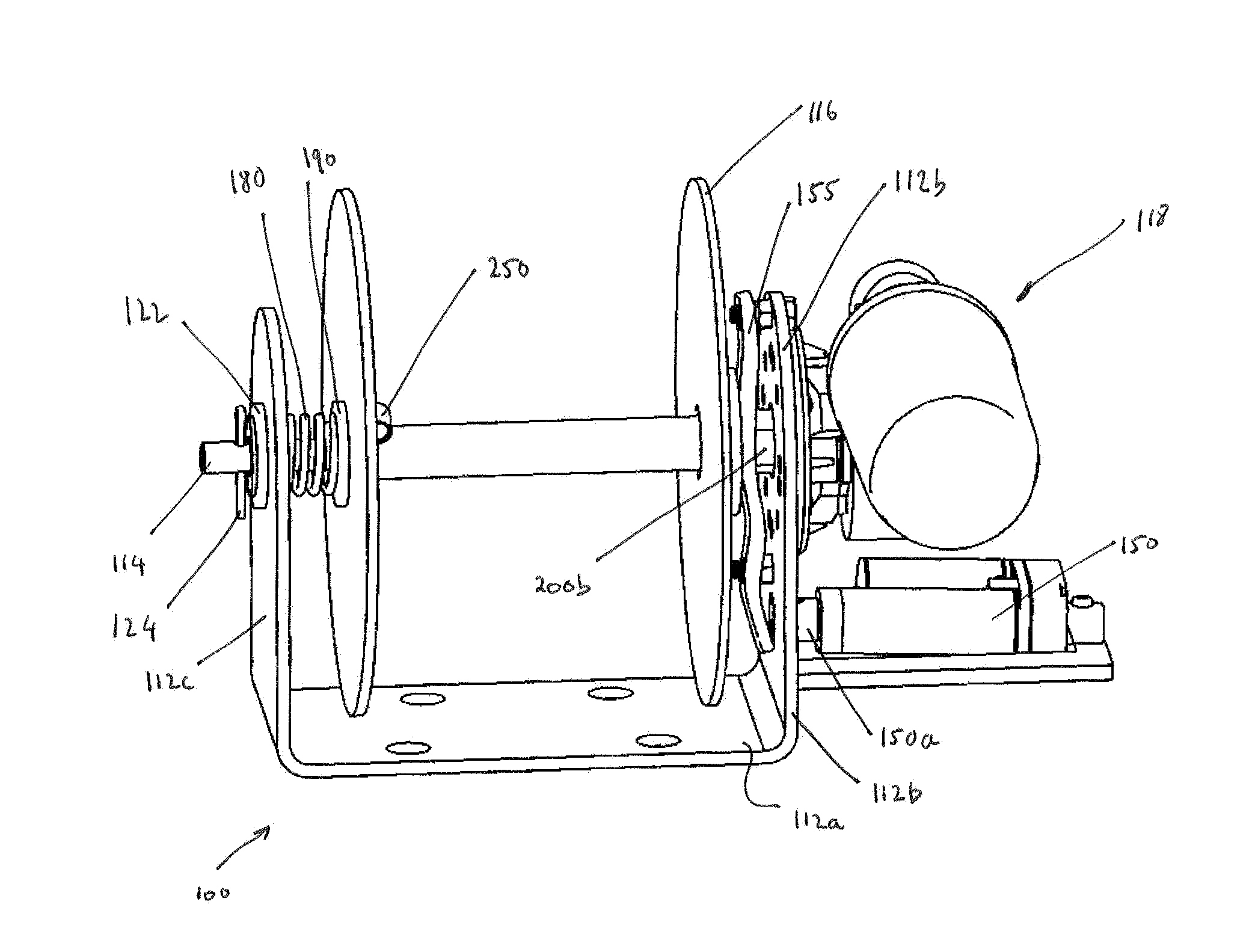
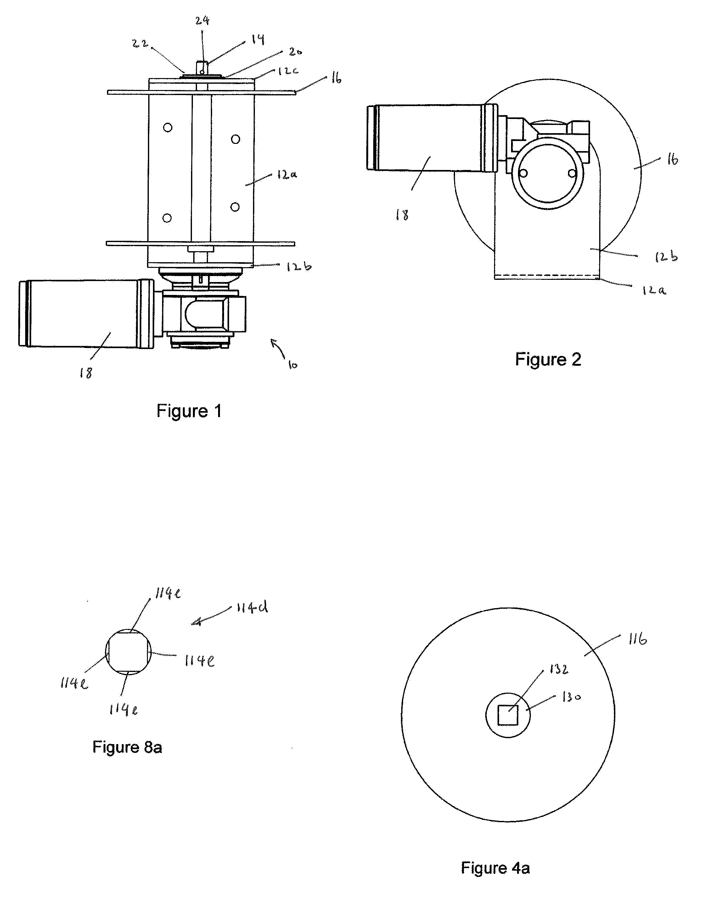
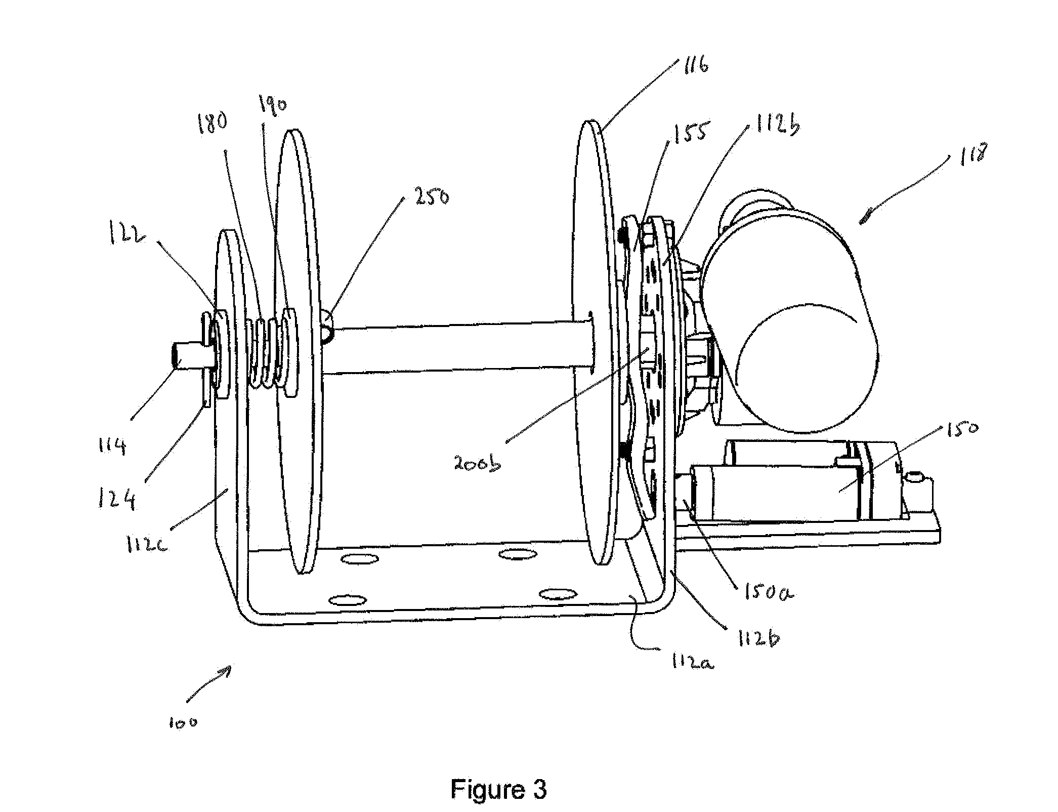
[0028]FIGS. 1 and 2 illustrate a prior art drum winch 10 for a marine vessel (not shown) that is used to lower and raise the vessel's anchor. The drum winch 10 includes a one piece mounting bracket (including a base plate 12a, an inner upright 12b and an outer upright 12c), a drive shaft 14, a drum 16 on which rode can be wound and a drive unit 18. Fasteners (not shown) extending through the base plate 12a of the mounting bracket 12 are used to securely mount the anchor drum winch 10 in the vessel's anchor well.

[0029]The drum 16 is in the form of a reel having a cylindrical hollow core. The drive shaft 14 extends through the core of the drum 16 and through a pair of bushes (not visible). The bushes mount the drum 16 on the drive shaft in such a manner as to ensure that the drum 16 only rotates with the drive shaft 14. Hence, when the drive shaft 14 is held stationary by the drive of the drive unit 18, the drum 16 is also prevented from rotating.

[0030]One end of the drive shaft 14 is...


PUM


Abstract

The invention relates to a drum winch (100) that is arranged to allow “free fall” of an anchor secured by rode to a drum (116) of the drum winch (100). The drum winch (100) includes a mounting bracket (112) and a drive shaft (114) arranged to be mounted to the mounting bracket (112) and coupled to the drive unit (118). The drum (116) is arranged relative to the drive shaft (1114) so that in a first mode of operation of the drum winch (100), the drum (116) can be rotated by rotation of the drive shaft (114). In a second mode of operation of the drum winch (100), the drum (116) is free to rotate relative to the drive shaft (114) so as to enable “free fall” of the anchor. The drum winch (100) further includes means for actuating (150) either the first mode of operation or the second mode of operation.

Description

CROSS REFERENCE[0001]This application claims priority from Australian Provisional Patent Application No. 2007906255 filed on 15 Nov. 2007, the contents of which are to be taken as incorporated herein by this reference.FIELD OF THE INVENTION[0002]The present invention relates to an improved drum winch. The drum winch has particular, but not exclusive, application in marine vessels as an anchor drum winch.BACKGROUND OF THE INVENTION[0003]Some marine vessels use a powered anchor drum winch to lower and then retrieve their anchor. The anchor is secured to the vessel by the rode. The rode may consist of all chain, all rope, or a combination of rope and chain. Such anchor drum winches are typically mounted in the vessel's anchor well. The rode is wound onto the drum of the winch avoiding the necessity to store the rode in the anchor well. This prevents tangling of the rode, negates the need to tie off the anchor rode and makes lowering and retrieval of the anchor very easy.[0004]A disadva...

Claims


Application Information

Patent Timeline
IPC IPC(8): B66D1/16
CPCB66D1/16B63B21/16
Inventor FORSTER, DEAN ROBERT
Owner STRESS FREE MARINE
Why Eureka
Try Eureka