Vehicle control system

Inactive Publication Date: 2015-10-01
TOYOTA JIDOSHA KK
View PDF1 Cites 5 Cited by
  • Summary
  • Abstract
  • Description
  • Claims
  • Application Information

AI Technical Summary

Benefits of technology

[0019]Thus, the vehicle control system according to the present invention is configured to execute the energy saving control such as the stop and start control and the coasting control in the vehicle in which the torque converter is disposed between the engine and the transmission, and the clutch device is disposed between the torque converter and the transmission. Specifically, during execution of the energy saving control, the vehicle control system brings the clutch device into engagement while increasing the torque transmitting capacity thereof using an increasing amount of a speed of the turbine runner as a target value. According to the present invention, therefore, an engagement shock of the clutch device and a resultant change in the output torque of the engine will not be transmitted to the transmission and the drive wheels through the torque converter and the clutch device. For this reason, the energy saving control such as the stop and start control and the coasting control can be carried out without providing uncomfortable feeling with the driver.
[0020]Optionally, the vehicle control system may be configured to promptly complete the engagement of the clutch device in case a difference between the input speed and the turbine speed

Problems solved by technology

However, the clutch control may not be carried out properly in the vehicle using the automatic transmission having the torque converter as taught by Japanese Patent Laid-Open No. 11-325232 during execution of the above-mentioned S & S control or the coasting control for automatically stopping and starting the engine.
Specifically, if the engine is stopped or restarted while keeping the clutch in engagement during exec

Method used


Image

  • Vehicle control system
  • Vehicle control system
  • Vehicle control system

Examples


Example

FIRST EXAMPLE

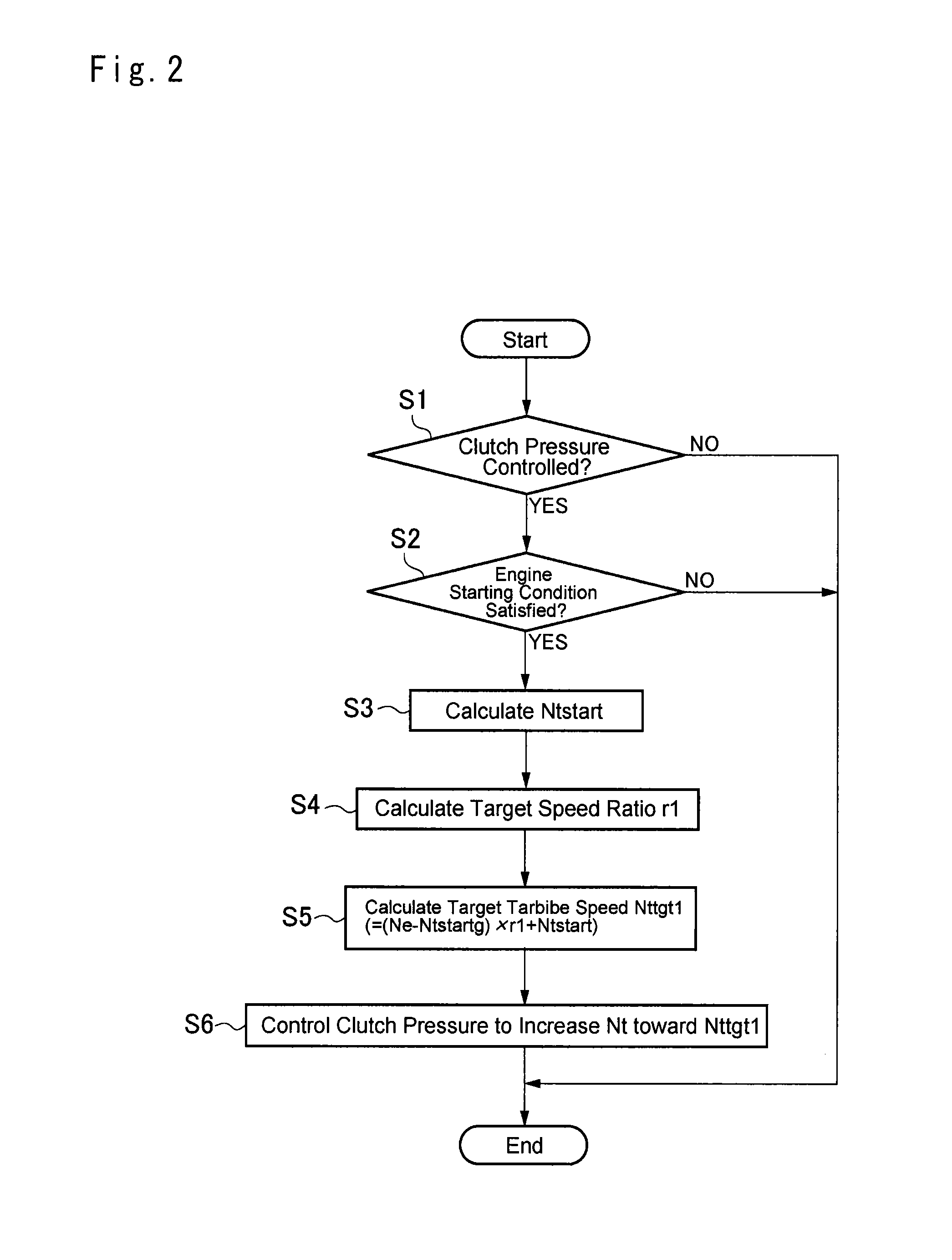
[0052]A first control example according to the present invention will now be explained with reference to the flowchart shown in FIG. 2. The routine shown in the FIG. 2 is executed during stopping the engine 1 by the S & S control, and repeated at predetermined short intervals. First of all, it is determined whether or not a pressure applied to the clutch device 7 is under control (at step S1). Specifically, if the clutch device 7 is in disengagement during the S & S control or gradually brought into engagement to start the engine 1, the pressure applied to the clutch device 7 is under control so that the answer of step S1 will be YES in those cases. By contrast, if the clutch device 7 is in complete engagement after the termination of the S & S control, the pressure applied to the clutch device 7 does not have to be controlled so that the answer of step S1 will be NO. In addition, the pressure applied to the clutch device 7 is also not necessary to be controlled if a sh...

Example

SECOND EXAMPLE

[0064]Thus, according to the first control example, the target turbine speed Nttgt1 is determined and the clutch device 7 is brought into engagement while slipping. In this case, if the target turbine speed Nttgt1 continuously falls below the input speed Nin, the engagement of the clutch device 7 will not be completed. For example, according to the example shown in FIG. 4, the coasting control is terminated when the accelerator pedal is depressed at point t21. At the same time, the engagement control of the clutch device 7 in disengagement during the coasting is commenced.

[0065]In this case, although the accelerator pedal is depressed, the accelerator is not opened widely, and the input speed Nin is slightly increased with an increment of the vehicle speed. In this situation, since an opening degree of the accelerator is small, the engine speed Ne is not increased significantly. Therefore, the engine speed Ne is continuously kept to be lower than the input speed Nin af...

Example

THIRD EXAMPLE

[0073]As described, according to the second control example, the turbine speed Nt is compulsory raised to the input speed Nin by bringing the clutch device 7 into engagement if the difference between the input speed Nin and the turbine speed Nt is not reduced over the time period T. In this case, it is preferable to bring the clutch device 7 into engagement as quick as possible in order to reduce friction of the clutch device 7 and in order not to slow acceleration response of the vehicle Ve.

[0074]For these purposes, according to the third control example, the turbine speed Nt is immediately raised to the input speed Nin if the input speed Nin is higher than the turbine speed Nt. Details of the third control example are shown in FIG. 7, and detailed explanations for the steps in common with those of the foregoing control examples will be omitted.

[0075]According to the third control example shown in FIG. 7, if the clutch device 7 is in disengagement or gradually brought ...


PUM


Abstract

A vehicle control system configured to carry out an energy saving control is provided. The vehicle control system is applied to a vehicle having an engine, a torque converter, a transmission and a clutch device selectively connecting a turbine runner to the transmission. The vehicle control system executes the energy saving control by controlling both an operating condition of the engine and an engagement condition of the clutch device or only the engagement condition of the clutch device. The vehicle control system comprises a clutch control means configured to increase the torque transmitting capacity of the clutch device using an increasing amount of a speed of the turbine runner as a target value, when bringing the clutch device into engagement being in disengagement during execution of the energy saving control.

Description

TECHNICAL FIELD[0001]The present invention relates to a vehicle control system for controlling a clutch device connecting a prime mover such as an engine to a transmission, and more specifically, to a vehicle control system for controlling a torque transmitting capacity of the clutch device in accordance with a torque applied thereto through a torque converter.BACKGROUND ART[0002]A required driving force for propelling a vehicle is varied during running. Basically, an energy efficiency of an engine of the vehicle would be degraded if operated at an operating point deviated away from an optimum operating point. In the conventional vehicles, therefore, a transmission is disposed on an output side of the engine to improve the energy efficiency by adjusting the driving force in accordance with a speed ratio of the transmission. To this end, for example, a geared transmission adapted to change a gear stage stepwise, and a continuously variable transmission adapted to vary a speed ratio c...

Claims


Application Information

Patent Timeline
IPC IPC(8): B60W30/192B60W10/02B60W10/06B60W30/20
CPCB60W30/192B60W30/20B60W2030/206B60W10/023B60W10/06B60W10/02F16H61/04F16H45/00F16H2045/005F16H2312/14F16D2500/50676F16D48/06F16D2500/50236F16D2500/50287F16D2500/5085F16D2500/50883F16D2500/70422F16D2500/70452F16D2500/70472Y02T10/60
Inventor YAMANAKA, SATOSHIYOKOKAWA, TAKAHIROITO, YOSHIO
Owner TOYOTA JIDOSHA KK
Why Eureka
Try Eureka