Heat dissipation module

Inactive Publication Date: 2009-01-01
INVENTEC CORP
View PDF4 Cites 3 Cited by
  • Summary
  • Abstract
  • Description
  • Claims
  • Application Information

AI Technical Summary

Benefits of technology

[0014]The heat dissipation module according to the present invention uses a driver to drive the first magnet on the linkage, and magnetic repulsion is used to reciprocately rotate the magnetic blades to generate an air flow to dissipate heat. Si

Problems solved by technology

As far Ultra Mobile PC (UMPC) is concerned, for instance, the temperature of its central processing unit (CPU), south bridge and north bridge is not easily to get overheated.
However, due to compact interior space of the UMPC, high temperature produced by the interior electronic devices makes the surface of the UMPC get ov

Method used


Image

  • Heat dissipation module
  • Heat dissipation module

Examples


Embodiment Construction

[0018]Reference will now be made in detail to the present preferred embodiments of the invention, examples of which are illustrated in the accompanying drawings. Wherever possible, the same reference numbers are used in the drawings and the description to refer to the same or like parts.

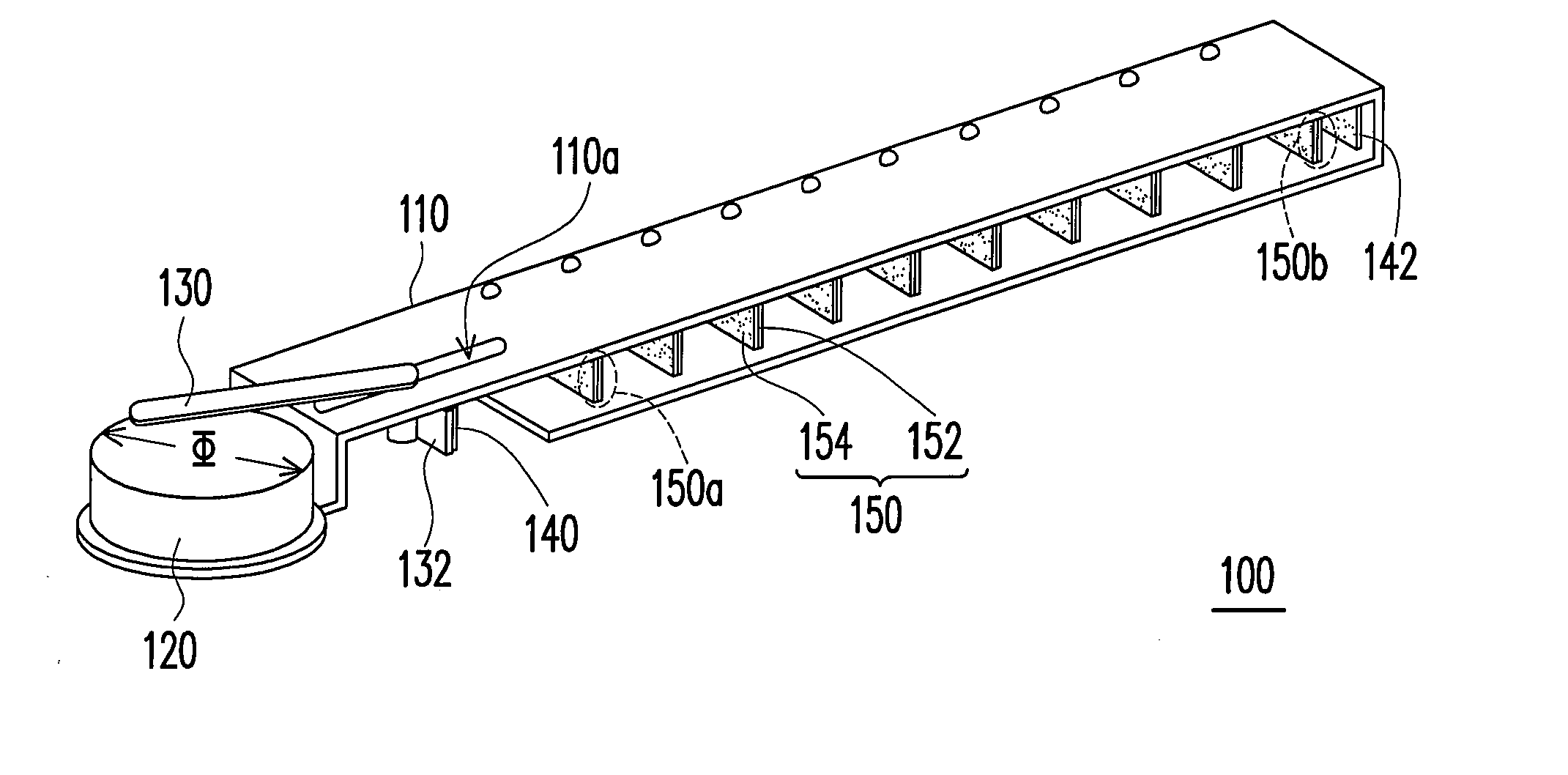
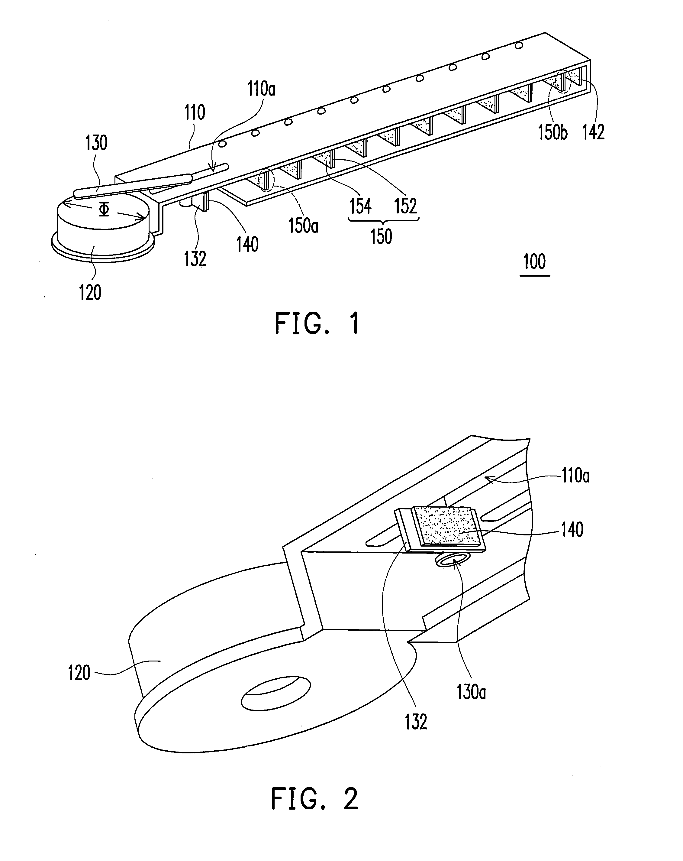
[0019]FIG. 1 is a schematic perspective view of a heat dissipation module according to an embodiment of the present invention, and FIG. 2 is a partially enlarged view of the heat dissipation module according to an embodiment of the present invention. Referring to FIG. 1 and FIG. 2, the heat dissipation module 100 in accordance with the present invention, includes a supporting frame 110, a driver 120, a linkage 130, a first magnet 140 and a plurality of magnetic blades 150. The supporting frame 110 comprises a chute 110a. The heat dissipation module 100 in accordance with the present invention may be mounted inside an interior of an Ultra Mobile PC (UMPC). However, this is only an example for illustra...


PUM


Abstract

A heat dissipation module including a supporting frame, a driver, a linkage, a first magnet and a plurality of magnetic blades is provided. The supporting frame has a chute. Moreover, one end of the linkage has a protrusion passing through the chute. The other end of the linkage is connected to the driver. The first magnet is disposed on the protrusion. In addition, the repelling magnetic blades are pivoted on the supporting frame. The outermost magnetic blade faces the first magnet and they repel each other.

Description

CROSS-REFERENCE TO RELATED APPLICATION[0001]This application claims the priority benefit of Taiwan application serial no. 96123763, filed on Jun. 29, 2007. All disclosure of the Taiwan application is incorporated herein by reference.BACKGROUND OF THE INVENTION[0002]1. Field of the Invention[0003]The present invention generally relates to a heat dissipation module, and more particularly, to a heat dissipation module occupying smaller space.[0004]2. Description of Related Art[0005]In recent years, with advancements of computer science and technology, the heat generated by electronic devices inside of a computer is increased while the computer runs more efficiently. To protect the electronic devices from being overheated, which would otherwise result in temporarily or even permanent damage of the electronic devices, several dissipation fan devices are usually provided inside the computer to produce active airflow in order to rapidly dissipate heat produced by the electronic devices to ...

Claims


Application Information

Patent Timeline
IPC IPC(8): F24F13/10
CPCF04D33/00F24F13/075H02K7/14H02K7/06F24F2013/148
Inventor WANG, SHAW-FUUHUANG, TING-CHIANGSHEN, SHIH-CHENSYU, SHENG-JIE
Owner INVENTEC CORP
Why Eureka
Try Eureka