Lamp using LED light source

a technology of led light source and led light source, which is applied in the direction of semiconductor devices for light sources, lighting and heating apparatus, instruments, etc., can solve the problems of poor pedestrian visibility, difficult to differentiate commercial products from others, and less attractive design features, etc., and achieves thin profile

Inactive Publication Date: 2010-10-14
STANLEY ELECTRIC CO LTD
View PDF36 Cites 42 Cited by
  • Summary
  • Abstract
  • Description
  • Claims
  • Application Information

AI Technical Summary

Benefits of technology

[0006]In contrast, the lamp 300 of FIG. 2 can achieve a novel appearance produced by the dispersed light projecting portions 340. In this configuration, however, the light projecting portions 340 must or should be disposed on a two-dimensional plane, and one can observe lighting points arranged just like a surface lighting system. Accordingly, the lamp can provide an appearance without a virtual depth and a three-dimensional sense, with less attractive design features. Furthermore, because of its specific structure, the center portion 350 where the LED light source 310 is disposed just below does not project light, and accordingly the area for projecting light may decrease by that area. This may disadvantageously diminish the visibility when seen by pedestrians.
[0007]The presently disclosed subject matter was devised in view of these and other problems and in association with the conventional art. According to an aspect of the presently disclosed subject matter, a lamp can provide an attractive appearance with a virtual depth or a three-dimensional sense, and a visibility when seen by pedestrians and the like as well as having a thin profile.
[0009]The lamp according to the above aspect of the presently disclosed subject matter can include an appropriate number of the individual light projecting surfaces and an appropriate number of the third total-reflecting surfaces disposed at respective appropriate positions. Accordingly, the lamp can achieve a novel appearance with a virtual depth or a three-dimensional sense rather than an appearance derived from a simple point source like the conventional lamp. Furthermore, the first lens portion can have the refractive surface disposed on the optical axis of the LED light source, so that the diffused light can be projected from the refractive surface. In this configuration, the central portion can be lit, and as a result, reduction of the light emission area can be prevented, thereby improving the visibility when seen by pedestrians. Namely, the configuration according to the present aspect of the disclosed subject matter can provide a lamp providing an attractive appearance with a virtual depth or a three-dimensional sense, and a visibility when seen by pedestrians and the like as well as having a thin profile.
[0011]According to the above aspect of the presently disclosed subject matter, the refractive surface can be a prismatic surface or a conical surface having a rotary axis on the optical axis of the LED light source. For example, the prismatic surface can be configured to diffuse the light on or adjacent the optical axis having the maximum luminance to the maximum degree while can converge the light, which enters farther from the optical axis, toward the center. This configuration can prevent the inferior appearance just like that derived from a point source. In addition, the second light-incident surface can be a wall-like or cylindrical lens surface having a rotary axis on the optical axis of the LED light source. This can further improve the light utilization efficiency.
[0016]According to the foregoing aspects of the presently disclosed subject matter, the lamp can provide an attractive appearance with a virtual depth or a perceived three-dimensional appearance, and a visibility when seen by pedestrians and the like as well as having a thin profile.

Problems solved by technology

Furthermore, its outer appearance has no attractive feature, so that it would be difficult to differentiate the commercial product from others.
In addition, as the lamp 200 of FIG. 1 can project light like that from a point source, the visibility when seen by pedestrians may be poor.
Accordingly, the lamp can provide an appearance without a virtual depth and a three-dimensional sense, with less attractive design features.
This may disadvantageously diminish the visibility when seen by pedestrians.

Method used


Image

  • Lamp using LED light source
  • Lamp using LED light source
  • Lamp using LED light source

Examples


Embodiment Construction

[0028]A description will now be made below to a lamp of the presently disclosed subject matter with reference to the accompanying drawings in accordance with exemplary embodiments.

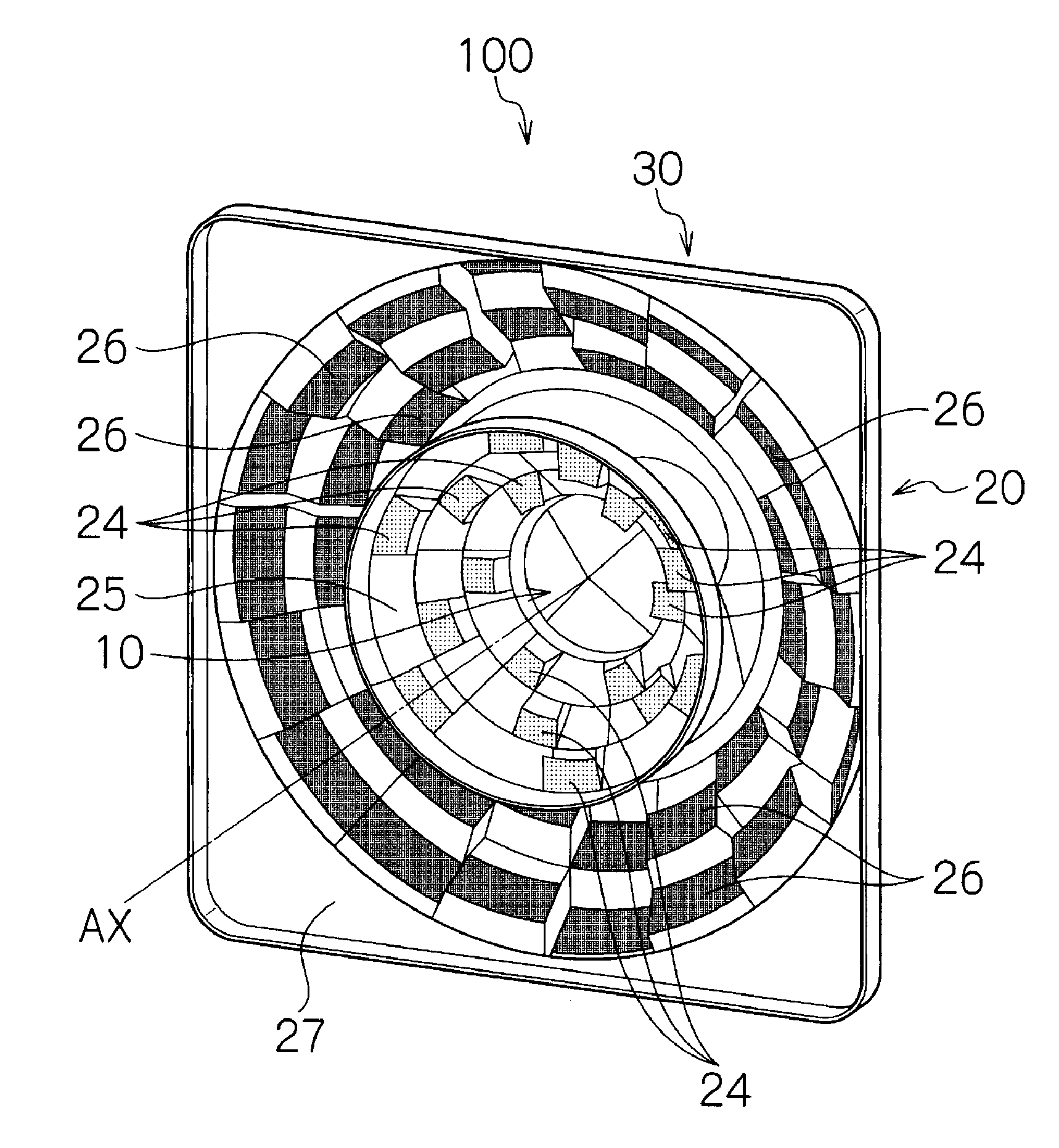
[0029]The lamp 100 of the present exemplary embodiment can be utilized in general lighting systems (such as, but not limited to, a downlight, a reading light, and an electric torch), vehicle signal lamps (such as, but not limited to, a tail lamp, a stop lamp, a turn signal lamp, a positioning lamp, and a daytime running lamp), and the like. As shown in FIGS. 4 to 6, the lamp 100 can include a lens body 30 and a chip-type LED light source 40 that has no specific directivity in terms of emission intensity. The lens body 30 can include a first lens portion 10 and a second lens portion 20 arranged outside the first lens portion 10, with the first lens portion 10 and the second lens portion 20 being integrally formed with each other using a transparent resin such as an acrylic resin or a polycarbonate resin. Th...


PUM


Abstract

A lamp can include an LED light source and a lens body having a first lens portion and a second lens portion arranged outside the first lens portion, the first and second lens portions being integrally formed with each other. The first lens portion can include a first light-incident surface and a refractive surface to form a main light distribution pattern condensation and refraction. The second lens portion can include a second light-incident surface, a first total-reflecting surface, a ring-shaped light projecting surface including an individual light projecting surface and a second total-reflecting surface, and a third total-reflecting surface. The second light-incident surface can be disposed beside the LED light source and can refract the light reaching the second light-incident surface to let the light enter the inside of the second lens portion. The first total-reflecting surface can totally reflect light entering through the second light-incident surface to condense the light in the front direction. The ring-shaped light projecting surface is disposed to cover an optical path range of light reflected from the first total-reflecting surface and is divided into a plurality of areas. The individual light projecting surface is provided in at least one of the plurality of divided areas and can transmit the light totally reflected from the first total-reflecting surface. The second total-reflecting surface can totally reflect the light from the first total-reflecting surface in the sideward and outward direction. The third total-reflecting surface can reflect light from the second total-reflecting surface to direct the light in the front direction.

Description

[0001]This application claims the priority benefit under 35 U.S.C. §119 of Japanese Patent Application No. 2009-097156 filed on Apr. 13, 2009, which is hereby incorporated in its entirety by reference.TECHNICAL FIELD [0002]The presently disclosed subject matter relates to a lamp using an LED light source, and in particular, relates to a lamp providing an attractive appearance with a virtual depth or a perceived three-dimensional appearance, and a visibility when seen by pedestrians and the like as well as having a thin profile.BACKGROUND ART [0003]A conventional lamp using an LED light source is illustrated in FIG. 1 (for example, see Japanese Patent Application Laid-Open No. Sho 60-130001). The lamp 200 includes an LED light source 210 without directional characteristics, and a cap-type lens 220 that can effectively utilize the light from the LED light source 210 by primary refraction and secondary refraction. Another conventional lamp is illustrated in FIG. 2 (for example, see Jap...

Claims


Application Information

Patent Timeline
Patent Type & Authority Applications(United States)
IPC IPC(8): H01K1/30
CPCF21S48/215F21S48/225F21S48/2262F21S48/2268F21S48/2287G02B19/0061F21V5/04F21V7/0091F21Y2101/02F21Y2105/001G02B19/0028F21V5/007F21Y2105/10F21Y2115/10F21S43/14F21S43/241F21S43/243F21S43/245F21S43/247
Inventor FUTAMI, TAKASHI
Owner STANLEY ELECTRIC CO LTD
Why Eureka
Try Eureka