Method and apparatus for motion artifact removal in multiple-exposure high-dynamic range imaging

a motion artifact and high-dynamic range technology, applied in the field of imagers, can solve the problems of image distortion, misregistration of the object in the combined image, and limited dynamic range on the upper end

Active Publication Date: 2010-10-14
APTINA IMAGING CORP
View PDF12 Cites 47 Cited by
  • Summary
  • Abstract
  • Description
  • Claims
  • Application Information

AI Technical Summary

Problems solved by technology

The dynamic range is limited on an upper end by the charge saturation level of the sensor, and on a lower end by noise imposed limitations and / or quantization limits of the analog-to-digital converter used to produce the digital image.
When the dynamic range of an image sensor is too small to accommodate the variations in light intensities of the imaged scene e.g., by having a low saturation level, image distortion may occur.
When the multiple images are combined using a basic multiple exposure combination method, the discrepancy in position and shape of the moving object in the multiple exposures will result in misregistration of the object in the combined image.
This may cause image artifacts such as a bright outline and / or a noisy region (see, e.g., FIG. 3, described in more detail below).
These image artifacts degrade the image and are undesirable.

Method used


Image

  • Method and apparatus for motion artifact removal in multiple-exposure high-dynamic range imaging
  • Method and apparatus for motion artifact removal in multiple-exposure high-dynamic range imaging
  • Method and apparatus for motion artifact removal in multiple-exposure high-dynamic range imaging

Examples


Embodiment Construction

[0019]In the following detailed description, reference is made to the accompanying drawings which form a part hereof, and in which are shown by way of illustration specific embodiments that may be practiced. It should be understood that like reference numbers represent like elements throughout the drawings. These example embodiments are described in sufficient detail to enable those skilled in the art to practice them. It is to be understood that other embodiments may be utilized, and that structural, material, and electrical changes may be made, only some of which are discussed in detail below.

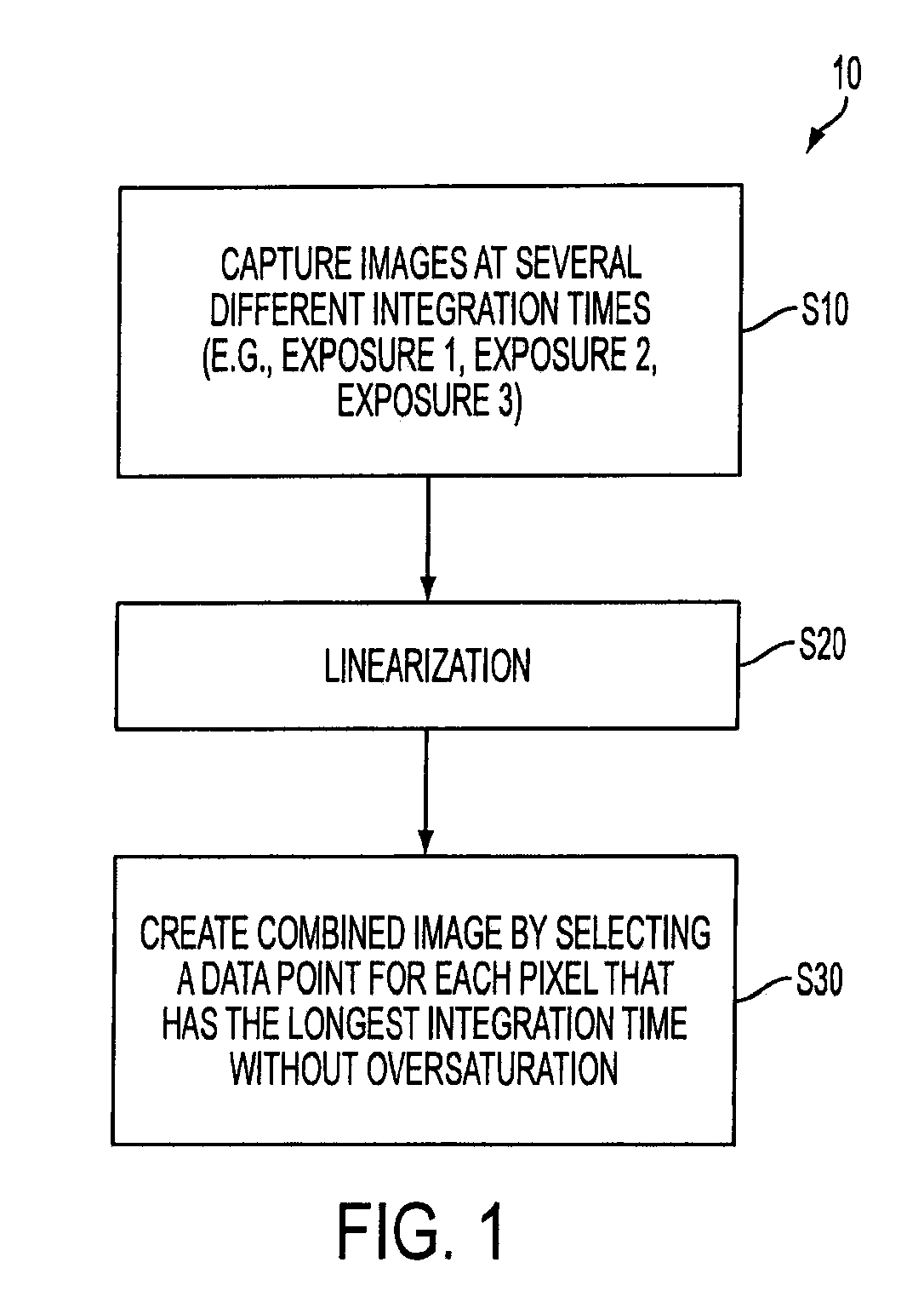
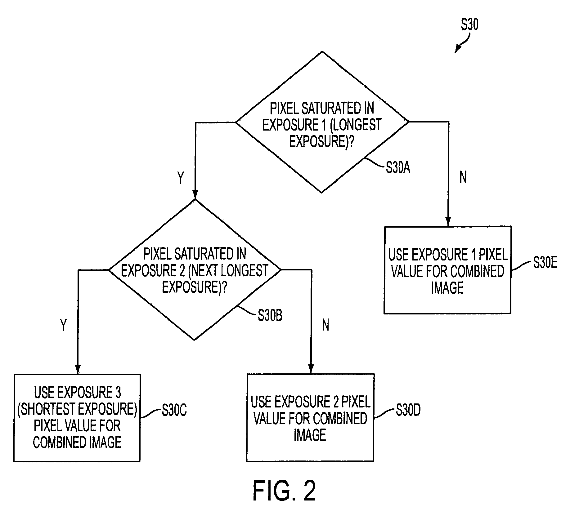
[0020]Disclosed embodiments relate to methods and apparatuses for detecting and removing image artifacts caused by motion which occur when using multiple-exposure high-dynamic range imaging. As previously discussed, multiple-exposure capture and combination is a common method of high-dynamic range imaging, however when scene or camera motion is present, misregistration can create an artifact ...


PUM


Abstract

Methods and apparatuses for correcting image artifacts in a high dynamic range image formed by combining a plurality of exposures taken at different integration periods. A determination is made as to whether there is motion between the exposures. If motion is detected, pixel signal values chosen are replaced with pixel signal values from another exposure.

Description

FIELD OF THE INVENTION[0001]Disclosed embodiments relate generally to imagers, and more particularly to methods and apparatuses for motion artifact removal in multiple-exposure high-dynamic range imaging.BACKGROUND OF THE INVENTION[0002]Many portable electronic devices such as cameras, cellular telephones, personal digital assistants (PDAs), MP3 players, computers and other devices include an imager for capturing images. One example of an imager is a complementary metal-oxide semiconductor (“CMOS”) imager. A CMOS imager includes a focal plane array of pixels, each one of the pixels including at least one photosensor overlying a substrate for accumulating photo-generated charge in the underlying portion of the substrate. Each pixel may include at least one electronic device such as a transistor for transferring charge from the photosensor to a storage region.[0003]Each pixel has corresponding readout circuitry that includes at least a charge storage region connected to the gate of an...

Claims


Application Information

Patent Timeline
Patent Type & Authority Applications(United States)
IPC IPC(8): H04N5/228H04N5/225
CPCH04N5/144H04N5/235H04N2101/00H04N5/374H04N5/2355H04N23/70H04N23/741H04N25/76
Inventor SAVIDGE, LAURA
Owner APTINA IMAGING CORP
Why Eureka
Try Eureka