Image processing apparatus, image forming apparatus and memory product

a technology of image processing and forming apparatus, which is applied in the direction of image enhancement, digitally marking record carriers, instruments, etc., can solve the problems of inconvenient real-time processing and difficulty in pipeline processes

Active Publication Date: 2010-10-14
SHARP KK
View PDF11 Cites 24 Cited by
  • Summary
  • Abstract
  • Description
  • Claims
  • Application Information

AI Technical Summary

Benefits of technology

[0024]By superimposing a color with a high luminance value over a color having low luminance value, the present invention implements the trapping process which does not change the size of an ...

Problems solved by technology

However, any specific method for this is not disclosed.
It is therefore difficult to perform a pipeline process on a pixel-by-pixel basis.
Therefore, since the maximum processing time necessary for the trapping process is unpredictable, the configuration d...

Method used


Image

  • Image processing apparatus, image forming apparatus and memory product
  • Image processing apparatus, image forming apparatus and memory product
  • Image processing apparatus, image forming apparatus and memory product

Examples


embodiment 1

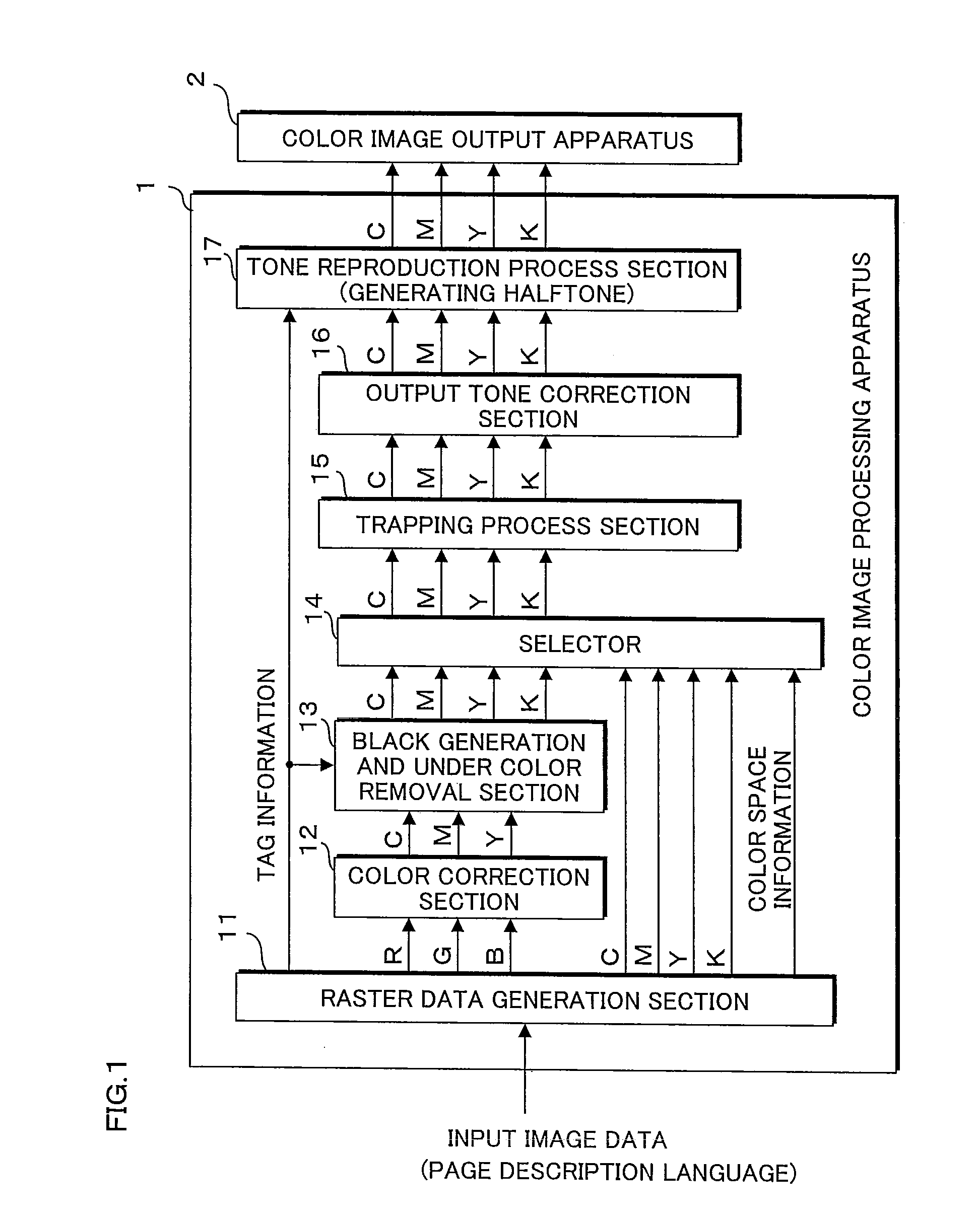
[0057]A color image forming apparatus according to Embodiment 1 will be explained below. FIG. 1 is a block diagram illustrating the configuration of the color image forming apparatus according to Embodiment 1. The color image forming apparatus of Embodiment 1 performs image processing for entered image data (hereinafter referred to as the input image data) and forms a color image on the basis of the processed image data on a sheet of recording paper etc. The input image data is created using application software, such as image editing software, on a computer, not shown. The created input image data is converted to a page description language by a printer driver and transmitted from the computer to the color image forming apparatus through a network.

[0058]As illustrated in FIG. 1, the color image forming apparatus comprises a color image processing apparatus 1 for processing input image data, and a color image output apparatus (image forming means) 2 for forming an image on the basis...

embodiment 2

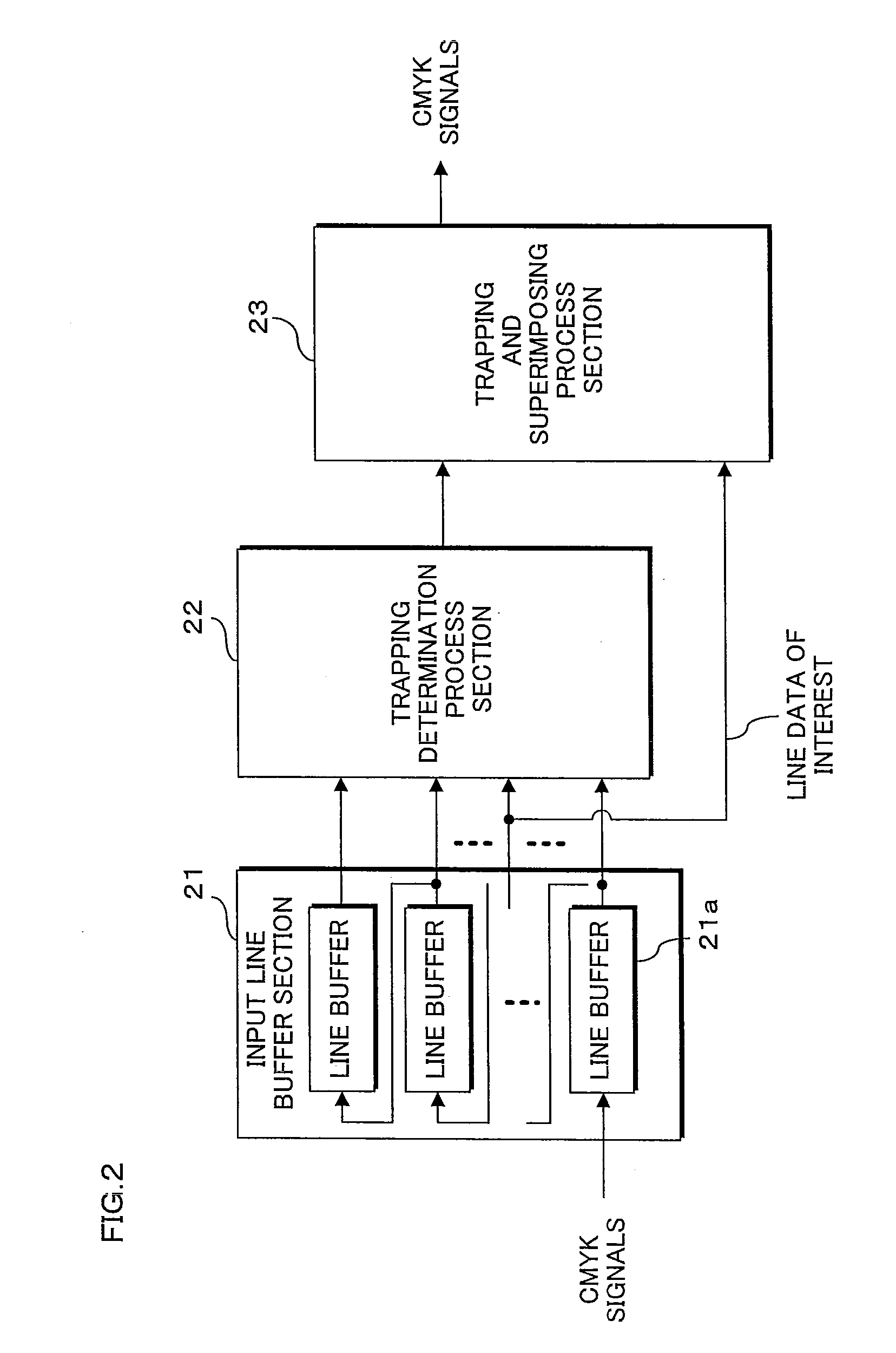
[0116]The following will explain a color image forming apparatus according to Embodiment 2. FIG. 16 is a block diagram illustrating the configuration of the color image forming apparatus according to Embodiment 2. The color image forming apparatus of Embodiment 2 is the color image forming apparatus of Embodiment 1 illustrated in FIG. 1, but includes a trapping / smoothing process section 18 instead of the trapping process section 15. Since other structures of the color image forming apparatus of Embodiment 2 are the same as those of the color image forming apparatus of Embodiment 1 illustrated in FIG. 1, explanations thereof will be omitted by designating the same reference codes to the same structures.

[0117]Like the raster data generation section 11 of Embodiment 1, the raster data generation section 11 of Embodiment 2 analyzes an input page description language and generates RGB or CMYK raster data. The raster data generation section 11 also obtains color space information of the i...


PUM


Abstract

A trapping determination process section calculates edge intensities in a main scanning direction and a sub scanning direction of each pixel by using differential filters for each color plane. The trapping determination process section determines, for at least two color planes, whether there is a pixel where the absolute values of the edge intensities are equal to or greater than a threshold and the edge intensities take positive and negative values, respectively. When such a pixel exists, the trapping determination process section calculates color differences between this pixel and the average values of the pixel values in an increment direction region and a decrement direction region, and determines a direction in which the color difference is smaller to be a similar color direction. The trapping determination process section determines, on the basis of the similar color direction, whether or not to perform a trapping process, and performs the trapping process.

Description

CROSS-REFERENCE TO RELATED APPLICATION[0001]This Non-provisional application claims priority under 35 U.S.C. §119(a) on Patent Application No. 2009-095182 filed in Japan on Apr. 9, 2009, the entire contents of which are hereby incorporated by reference.BACKGROUND[0002]1. Technical Field[0003]The present invention relates to an image processing apparatus, an image forming apparatus, and a memory product for performing a process of superimposing pixel data of a plurality of color components.[0004]2. Description of Related Art[0005]A trapping process, a smoothing process etc. are proposed to prevent degradation of image quality of an image formed on a paper medium by an image forming apparatus, such as a copying machine and a printer. The process of superimposing pixel data of a plurality of color components (hereinafter referred to as the trapping process) is a process for preventing white gaps from appearing when a misregistration occurs and a page background has been exposed. The sm...

Claims


Application Information

Patent Timeline
IPC IPC(8): G06K9/00G06F15/00
CPCH04N1/58
Inventor SAKAMOTO, AKIRA
Owner SHARP KK
Why Eureka
Try Eureka