Image shake correction apparatus and image pickup apparatus

a technology of image pickup and shake correction, which is applied in the field of image shake correction apparatus, can solve the problems of accuracy and workability deterioration, and achieve the effects of reducing size, maintaining accuracy and workability, and improving assembly productivity

Inactive Publication Date: 2010-10-14
CANON KK
View PDF1 Cites 11 Cited by
  • Summary
  • Abstract
  • Description
  • Claims
  • Application Information

AI Technical Summary

Benefits of technology

[0008]The present invention provides an image shake correction apparatus which is reduced in size and improves the assemble productivity while maintaining accuracy and workability, and an image pickup apparatus having the image shake correction apparatus.

Problems solved by technology

Further, an error component is increased by adding parts such as a slider and therefore the accuracy and the workability may be deteriorated in moving the correction optical system to a desired position.

Method used


Image

  • Image shake correction apparatus and image pickup apparatus
  • Image shake correction apparatus and image pickup apparatus
  • Image shake correction apparatus and image pickup apparatus

Examples


Embodiment Construction

[0021]Exemplary embodiments of the present invention will be described below with reference to the accompanied drawings.

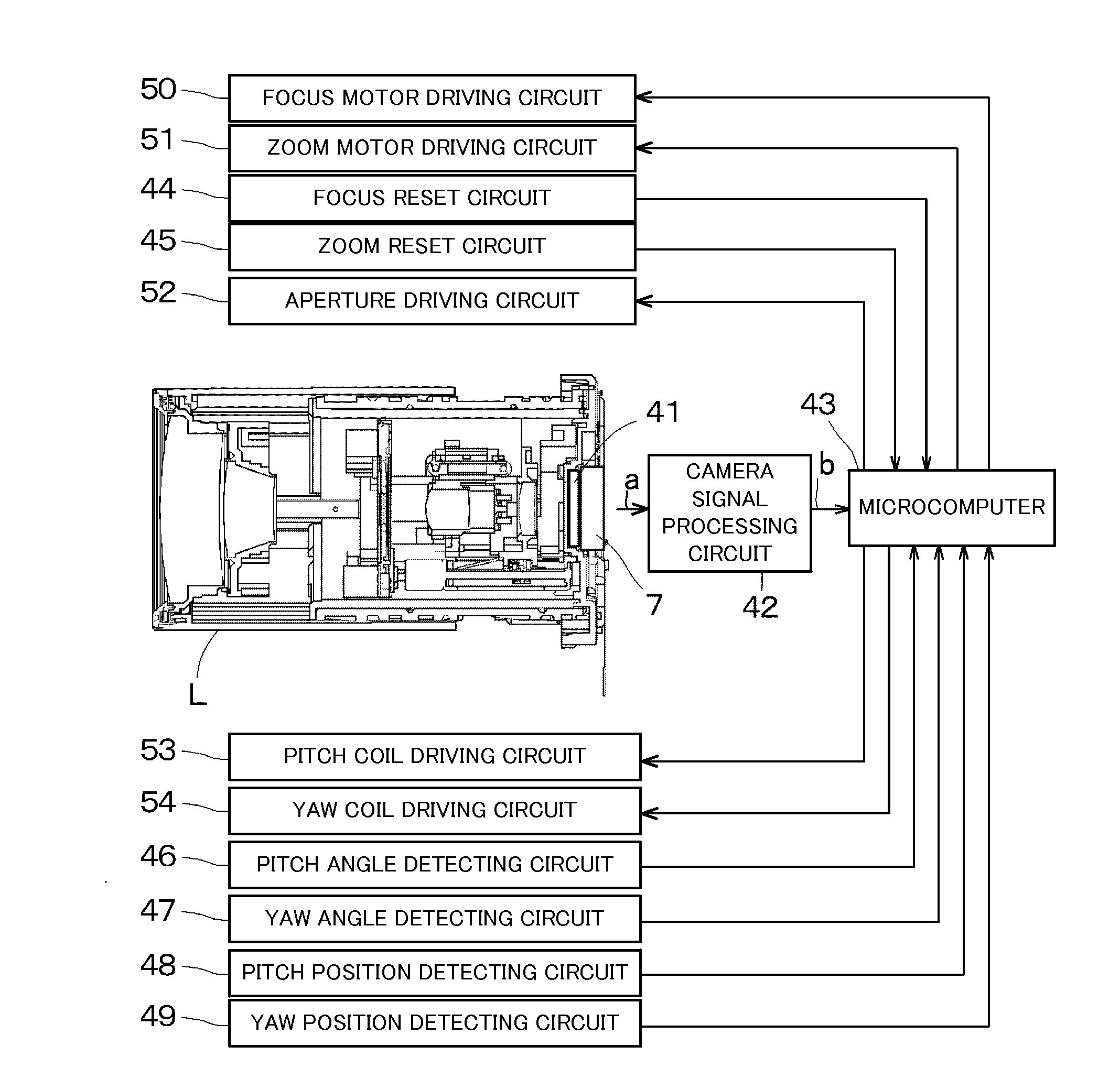
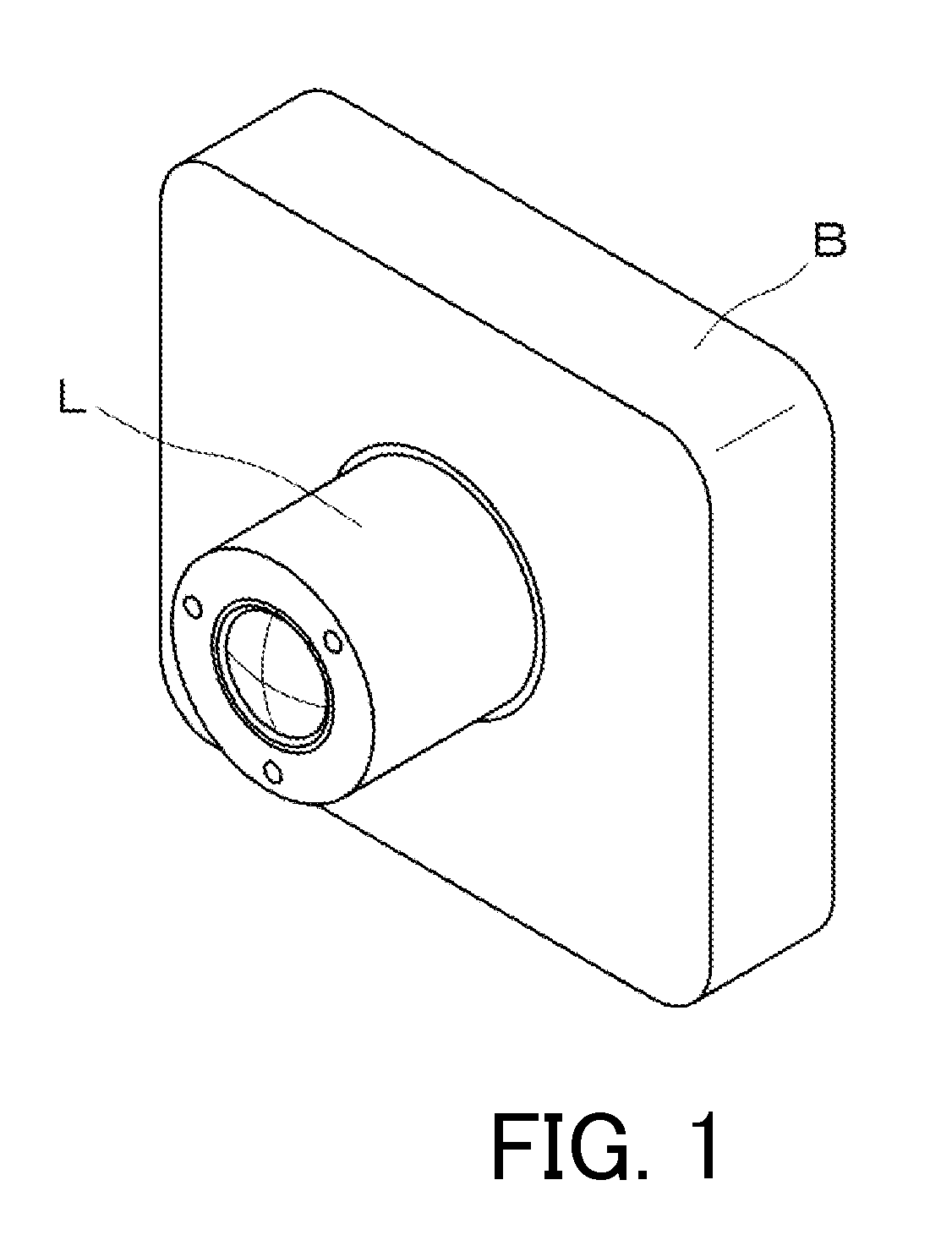
[0022]FIG. 1 shows a perspective view of an image pickup apparatus such as a video camera or a digital camera (hereinafter, referred to as a camera) of the embodiment. A lens barrel L capable of zooming is attached to the front of a camera body B, and a silver salt film or an image pickup element for recording an object image formed by an image pickup optical system in the lens barrel L is housed in the camera body B.

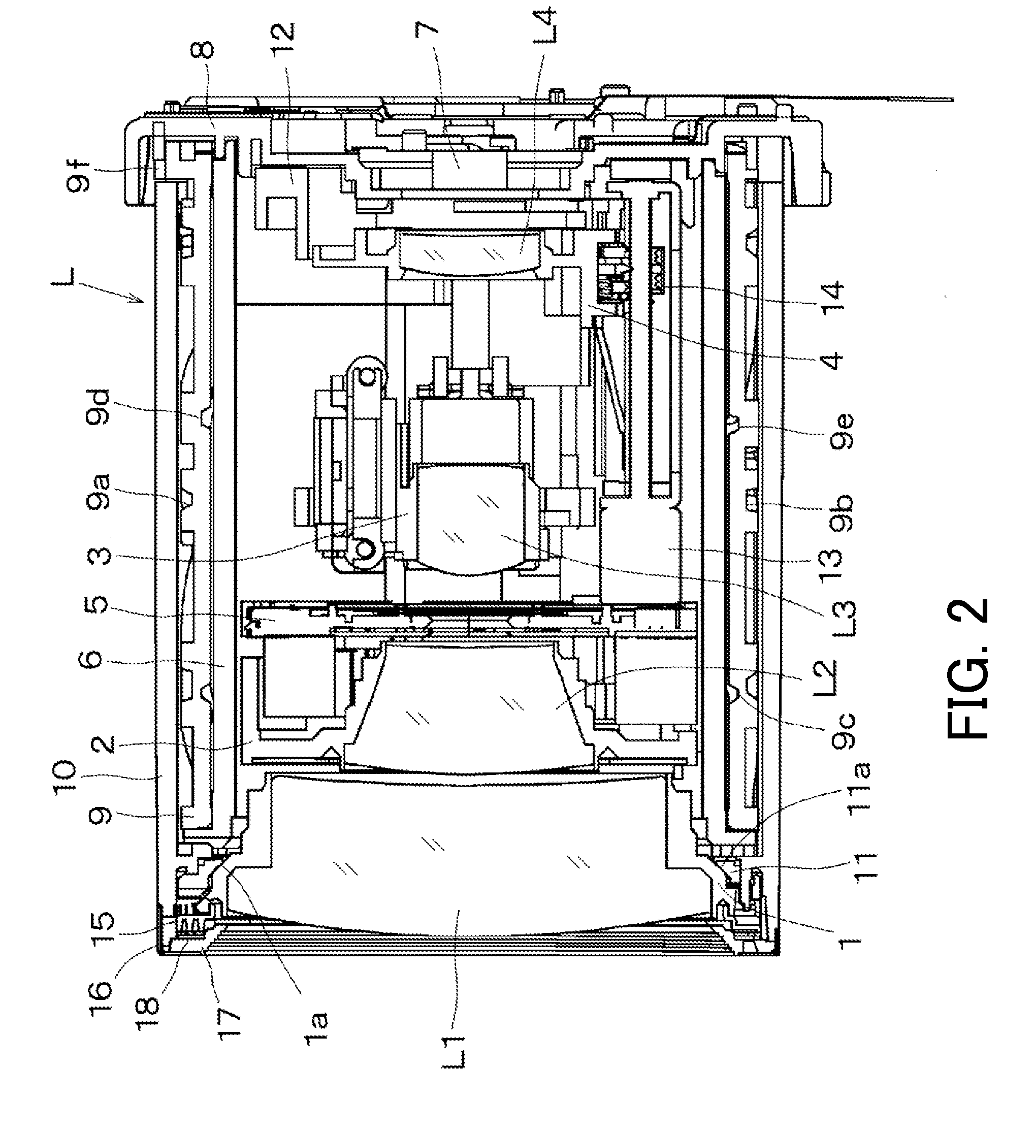
[0023]FIGS. 2 to 4 are cross-sectional views of the lens barrel L. The lens barrel L has a magnification varying optical system configured by four groups and is a so-called retractable lens barrel where the interval of each lens group is narrowed in a non-use state relative to the interval during a normal use to considerably shorten a total lens length. FIG. 2 is a cross-sectional view of a main part of the lens barrel in a retracted condition, FIG. 3 ...


PUM


Abstract

A third group barrel 3 holding a third lens group L3 is controlled to be driven by drivers in yaw and pitch directions orthogonal to an optical axis, respectively. The Y magnet and the Y yoke of the driver in the yaw direction are fixed on the third group barrel 3, and a Y electromagnetic coil is disposed at a Y guide base 24 surrounding the third group barrel 3. As a driver in the pitch direction, a P magnet and P yoke 29 are fixed to the Y guide base 24, and a P electromagnetic coil is fixed to a P guide base at an opposed position. A Y guide bar 25 and a P guide bar 30 are overlapped with projection regions onto planes orthogonal to the optical axis of the Y electromagnetic coil and the Y magnet, and the P electromagnetic coil and the P magnet, respectively.

Description

BACKGROUND OF THE INVENTION[0001]1. Field of the Invention[0002]The present invention relates to an image shake correction apparatus of an optical device such as an image pickup apparatus, for example a video camera or a digital still camera, or an interchangeable lens apparatus.[0003]2. Description of the Related Art[0004]A conventional image shake correction apparatus is disclosed in Japanese Patent No. 2641172. The apparatus moves an image shake correction optical system that is a part of an image pickup optical system in two directions on a plane substantially orthogonal to an optical axis to change the optical axis of the image pickup optical system in order to correct the image shake which is generated by the shake of a camera when taking an image.[0005]As a structure of such an image shake correction apparatus, commonly, two driving sources are provided for driving the image shake correction lens in two directions orthogonal to the optical axis and the driving sources are dis...

Claims


Application Information

Patent Timeline
Patent Type & Authority Applications(United States)
IPC IPC(8): G03B17/00G02B27/64
CPCG03B17/00G02B27/646
Inventor KATO, YUICHIRO
Owner CANON KK
Why Eureka
Try Eureka