Component mounting board structure and production method thereof

a technology of mounting board and components, applied in the direction of printed circuit aspects, electrical apparatus construction details, printed circuit non-printed electric components association, etc., can solve the problems of influence on the non-heat generating component achieve the effect of low heat resistance, high heat resistance, and low heat resistan

Inactive Publication Date: 2010-02-16
ORMON CORP
View PDF13 Cites 11 Cited by
  • Summary
  • Abstract
  • Description
  • Claims
  • Application Information

AI Technical Summary

Benefits of technology

[0026]In accordance with the first aspect of the invention, the heat radiation or heat block is performed with the resin among the low heat-resistance heat generating component mounting region, the high heat-resistance heat generating component mounting region, the low heat-resistance non-heat generating component mounting region, and the high heat-resistance non-heat generating component mounting region. Therefore, the resin functions not only as the radiation member layer but also as the heat block layer, and a small heat amount generated by the low heat-resistance heat generating component is transferred to the component mounting board. However, the heat transferred to the component mounting board can be radiated by efficiently inducing the heat to a point where the heat has no influence on the neighbors such as the electronic device housing, and particularly the heat never has an influence on the low heat-resistance non-heat generating component.
[0064]In accordance with the component mounting board structure production method of the invention, the versatile component mounting board structure having the radiation or heat block structure can be produced at low cost according to the component mounting boards such as the printed wiring board and the lead frame board, and the assembling productivity can be improved.

Problems solved by technology

However, the heat transferred to the component mounting board can be radiated by efficiently inducing the heat to a point where the heat has no influence on the neighbors such as the electronic device housing, and particularly the heat never has an influence on the low heat-resistance non-heat generating component.

Method used


Image

  • Component mounting board structure and production method thereof
  • Component mounting board structure and production method thereof
  • Component mounting board structure and production method thereof

Examples


example 1

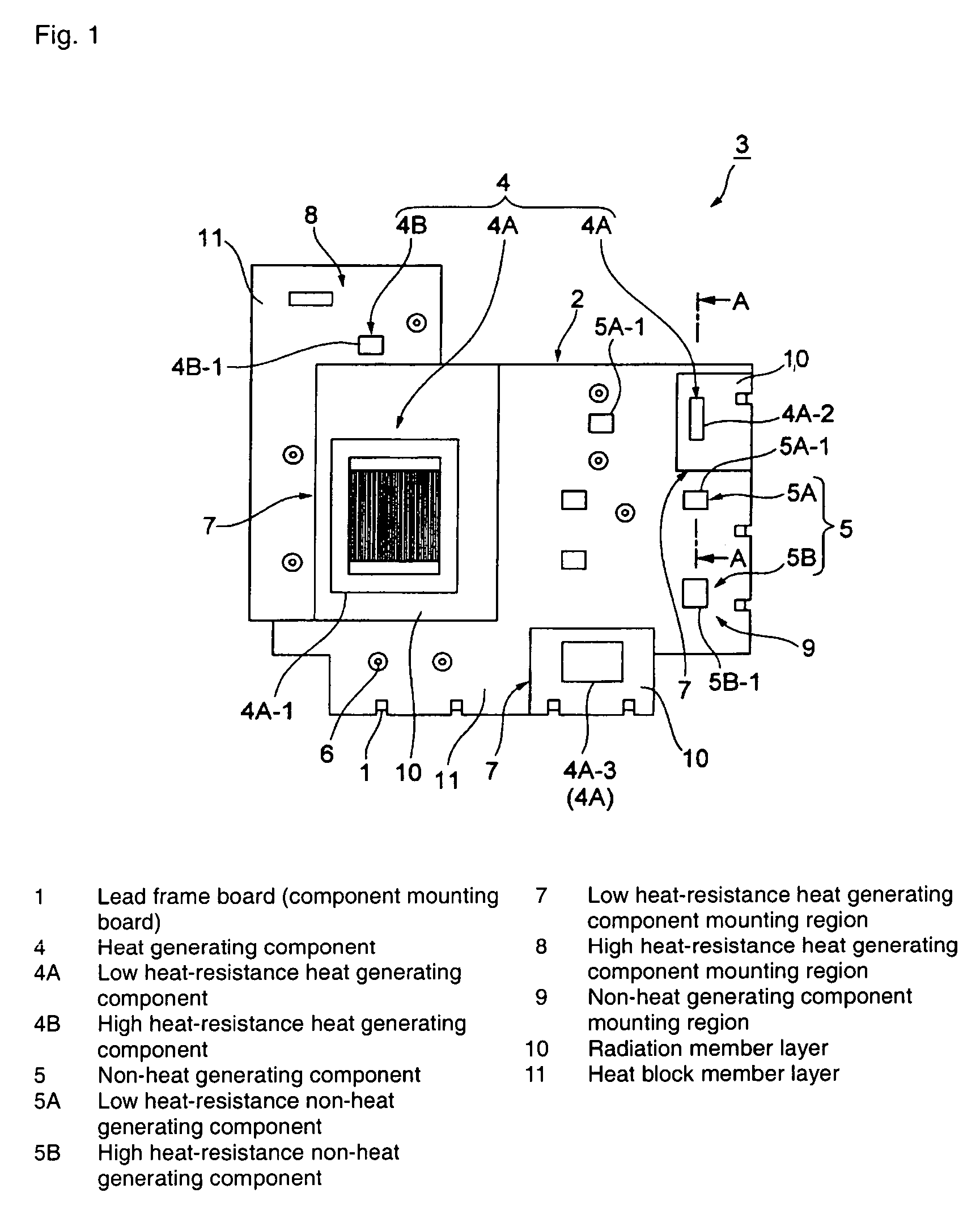
[0116]Example 1 Shown in FIG. 2 will be Described Below.

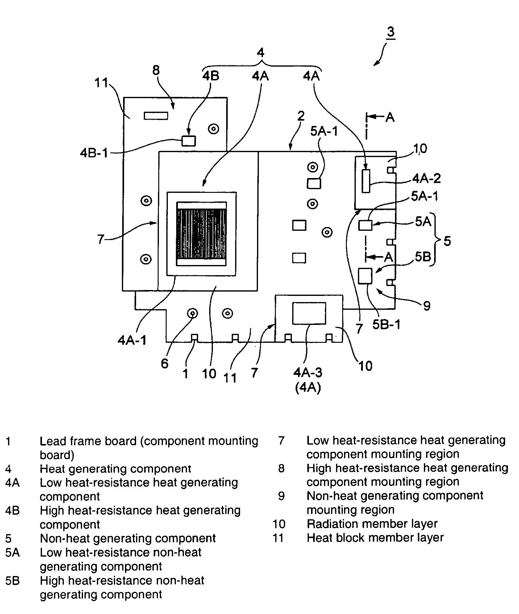
[0117]Referring to FIG. 2, the transistor 4A-2 which is of the low heat-resistance heat generating component 4A and the aluminum electrolytic capacitor 5A-1 which is of the low heat-resistance non-heat generating component 5A are mounted in the lead frame board 1. The resin layer 2 is configured by forming the radiation member layer 10 made of the resin having the relatively high thermal conductivity in the low heat-resistance heat generating component mounting region 7 where the transistor 4A-2 is mounted in the component mounting surface 1A and the backside 1B of the lead frame board 1. The resin layer 2 is also configured by forming the heat block member layer 11 made of the resin having the relatively high thermal conductivity in the non-heat generating component mounting region 9 (or high heat-resistance heat generating component mounting region 8) where the aluminum electrolytic capacitor 5A-1 is mounted in the component ...

example 2

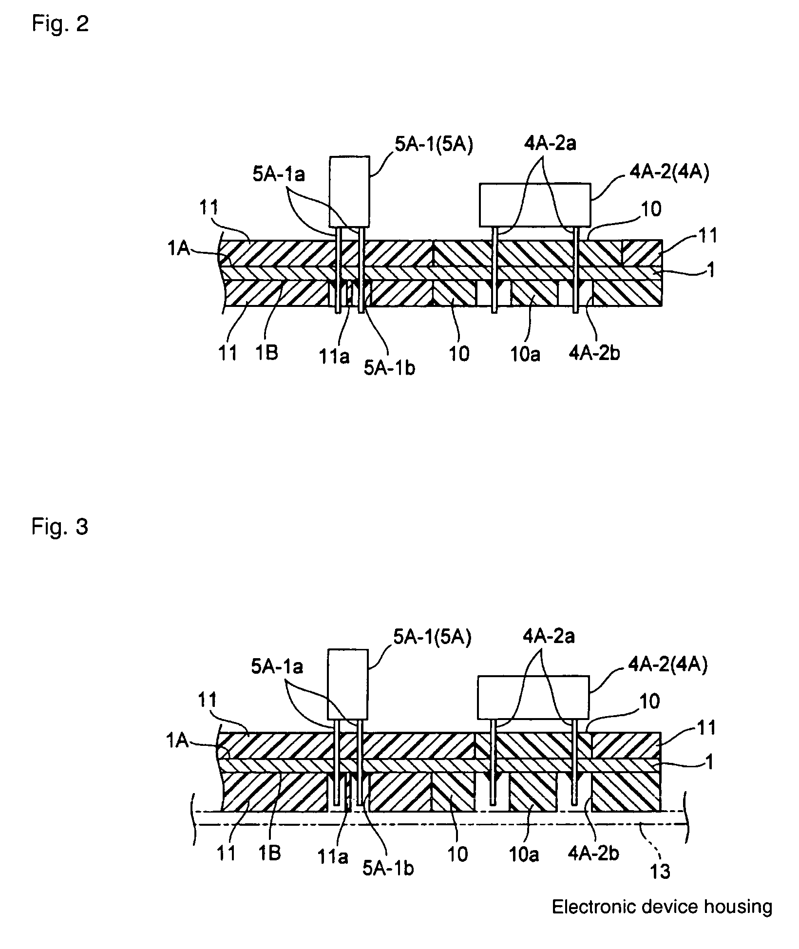
[0124]FIG. 3 Shows Example 2 of the Invention.

[0125]Example 2 is a modification of Example 1. Example 2 differs from Example 1 in that thicknesses of the radiation member layer 10 and heat block member layer 11 are increased such that the lead foot pieces 4A-2a of the transistor 4A-2 or the lead foot pieces 5A-1a of the aluminum electrolytic capacitor 5A-1 are not projected from lower surfaces of the radiation member layer 10 and heat block member layer 11 and the lower surfaces of the radiation member layer 10. Example 2 also differs from Example 1 in that the lower surfaces of the radiation member layer 10 and heat block member layer 11 are brought into close contact with an electronic device housing 13. The electronic device housing 13 also exerts the radiation function to achieve the efficient radiation.

[0126]In the case where the heat transfer is obstructed due to the incomplete contact caused by surface roughness or warpage of the radiation member layer 10, the heat block memb...

example 3

[0127]FIG. 4 Shows Example 3 of the Invention.

[0128]Example 1 has a configuration in which the end portions of the radiation member layer 10 and heat block member layer 11 are bright into contact with each other without gap. On the contrary, Example 3 shown in FIG. 4 differs from Example 1 in that the end portions of the radiation member layer 10 and heat block member layer 11 are separated from each other with a gap S. Other configurations of Example 3 are similar to those of Example 1.

[0129]In the configuration of Example 3, the heat block can securely be performed between the radiation member layer 10 and the heat block member layer 11 by forming the gap S between the radiation member layer 10 and the heat block member layer 11 on the lead frame board 1. Therefore, the transistor 4A-2 can be protected such that the heat generated by the chip type resistor 4B-1 which is of the high heat-resistance heat generating component 4B has no influence on the transistor 4A-2 which is of the...


PUM


Abstract

In a lead frame board, while a heat radiation wall member formed by a resin having a relatively high thermal conductivity is provided in a low heat-resistance heat generating component mounting region where a low heat-resistance heat generating component is mounted, heat block wall members formed by resins having relatively low thermal conductivities are provided in a high heat-resistance heat generating component mounting region where a high heat-resistance heat generating component is mounted and in a non-heat generating component mounting region where a non-heat generating component is mounted. Thus, heat block is performed between the low heat-resistance heat generating component mounting region and the high heat-resistance heat generating component mounting region and non-heat generating component mounting region, and a heat radiation function is enhanced in the low heat-resistance heat generating component.

Description

BACKGROUND OF THE INVENTION[0001]1. Field of the Invention[0002]The present invention relates to a component mounting board structure having a heat radiation or heat block function and a production method thereof. The component mounting board structure is configured such that heat generated from a heat generating component, e.g., a heat generating element of an electronic device such as a switching regulator and a thermoregulator is efficiently radiated while does not have an influence on other components through a component mounting board.[0003]2. Description of the Related Art[0004]Recently, in the electronic devices such as the thermoregulator, development focuses on high functionality. However, heat radiation measures obstruct miniaturization and high performance of the electronic device.[0005]In the heat radiation measures of the electronic device, there is a problem that electric power consumption of the electronic device is increased due to the high functionality of the elect...

Claims


Application Information

Patent Timeline
Patent Type & Authority Patents(United States)
IPC IPC(8): H05K7/00
CPCH05K1/0201H05K1/0203H05K3/284H05K1/0284H05K1/0373H05K1/185H05K3/202H05K3/301H05K3/3447H05K2201/0187H05K2201/0209H05K2201/0394H05K2201/062H05K2201/09045H05K2201/09063H05K2201/09118H05K2201/09972H05K2201/2036H05K2203/1316H05K7/20
Inventor TANAKA, HIROKAZUISHIBASHI, HIROYUKI
Owner ORMON CORP
Why Eureka
Try Eureka