Airbag mounting assembly for vehicles

a technology for mounting assemblies and airbags, which is applied in the direction of vehicular safety arrangements, roofs, pedestrian/occupant safety arrangements, etc., can solve the problems of increasing production costs, reducing product weight and manufacturing costs, etc., to achieve the effect of improving the productivity of airbag mounting assemblies, and reducing the number of working steps

Active Publication Date: 2011-05-19
HYUNDAI MOTOR CO LTD +1
View PDF25 Cites 10 Cited by
  • Summary
  • Abstract
  • Description
  • Claims
  • Application Information

AI Technical Summary

Benefits of technology

[0029]First, the present invention can mount a passenger airbag both to a crush pad and to a cowl cross bar using a common mounting bracket, so that the present invention can simplify the construction of the airbag mounting assembly and can reduce the number of working steps, the product weight and the manufacturing cost of the airbag mounting assembly, thereby improving productivity of the airbag mounting assembly.
[0030]Second, unlike conventional airbag mounting assemblies which must be separately produced for different design factors determined by vehicle models, the present invention integrates the different design factors into one mounting bracket, thus simplifying the design of airbags and efficiently producing products.

Problems solved by technology

However, the conventional airbag is problematic in that, because the airbag requires a plurality of brackets to improve the efficiency with which the airbag module is assembled to the cowl cross bar and is assembled to make contact with the circular shape of the cowl cross bar 20, the plurality of brackets increase the production cost and complicate the assembly process of the airbag, and require an excessively large installation space for the airbag.
In other words, the space defined between the airbag module and the cowl cross bar is reduced due to the excessive number of brackets, so that it is difficult to secure a desired mounting flat part in the space.

Method used


Image

  • Airbag mounting assembly for vehicles
  • Airbag mounting assembly for vehicles
  • Airbag mounting assembly for vehicles

Examples


Embodiment Construction

[0043]Reference will now be made in detail to various embodiments of the present invention(s), examples of which are illustrated in the accompanying drawings and described below. While the invention(s) will be described in conjunction with exemplary embodiments, it will be understood that present description is not intended to limit the invention(s) to those exemplary embodiments. On the contrary, the invention(s) is / are intended to cover not only the exemplary embodiments, but also various alternatives, modifications, equivalents and other embodiments, which may be included within the spirit and scope of the invention as defined by the appended claims.

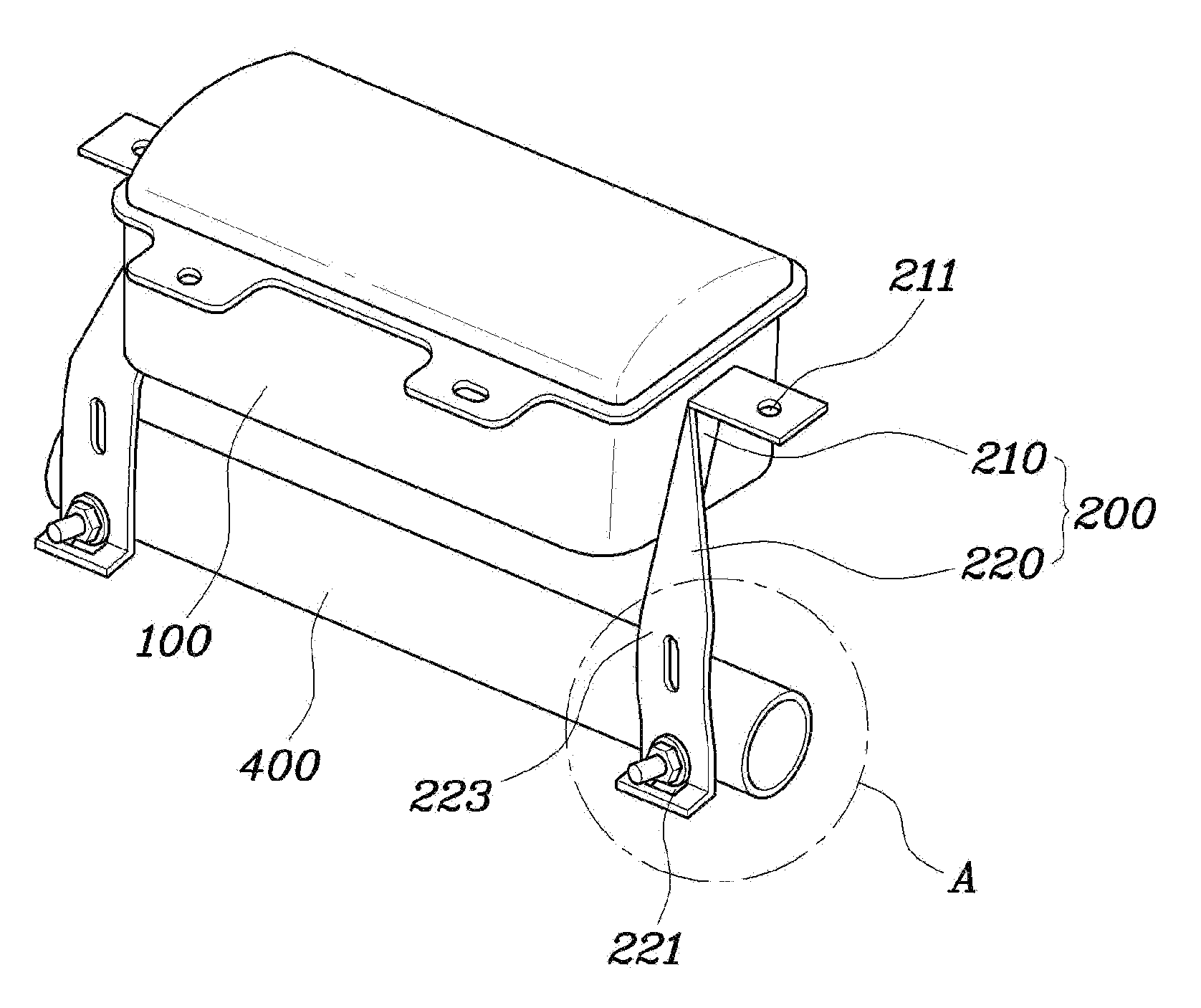
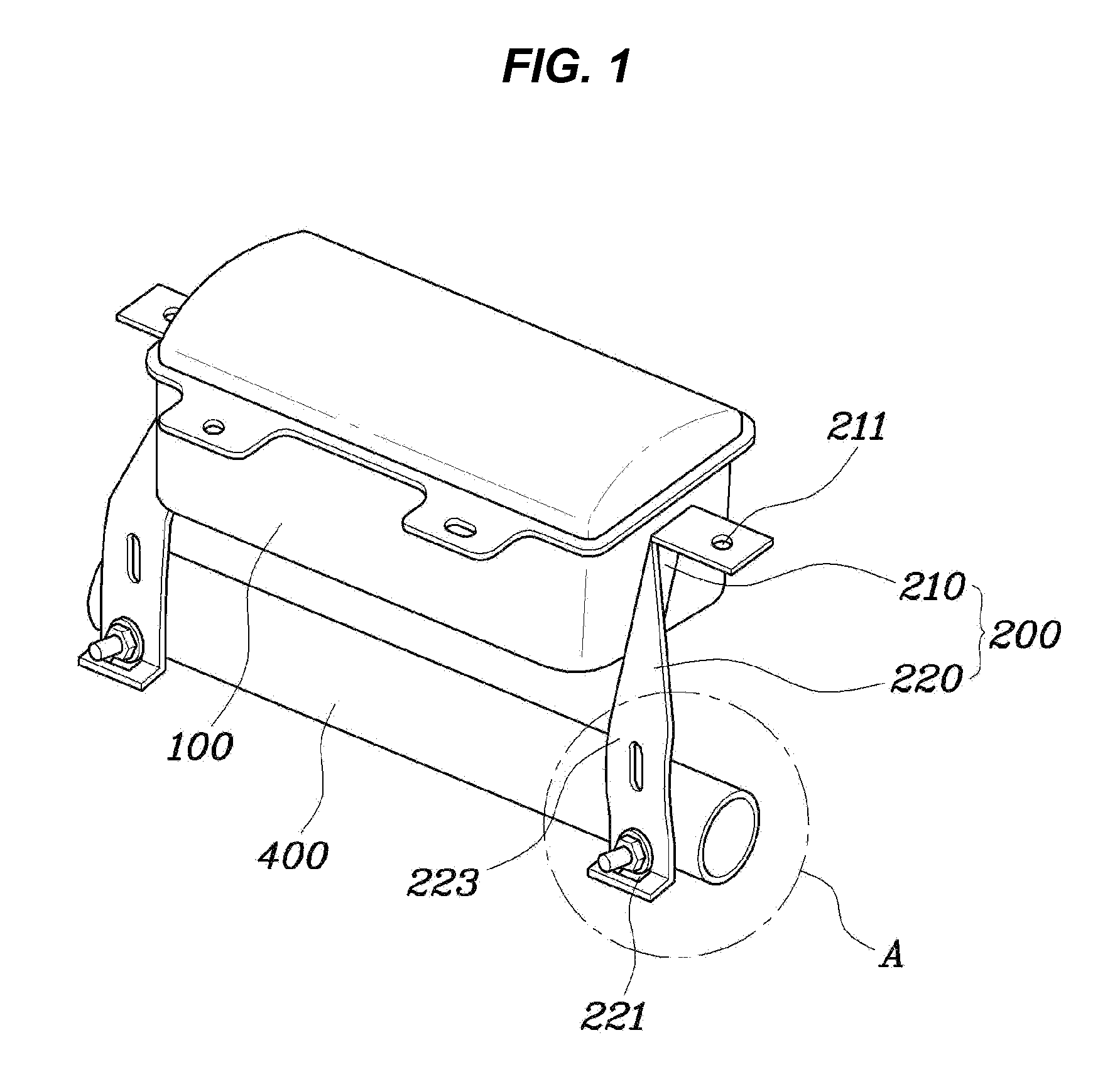
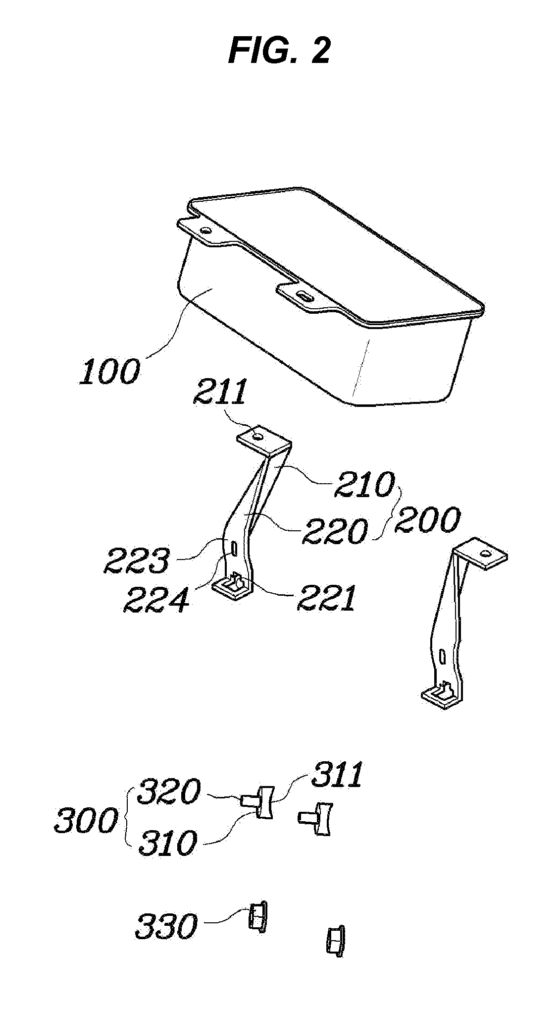
[0044]FIG. 1 is a perspective view illustrating an assembled state of an airbag mounting assembly for a vehicle according to an embodiment of the present invention. FIG. 2 is an exploded perspective view illustrating the airbag mounting assembly for a vehicle according to the embodiment of the present invention. FIG. 3 is a view illus...


PUM


Abstract

An airbag mounting assembly for vehicles to mount a passenger airbag housing to a cowl cross bar may include a mounting bracket, a first end thereof being mounted to the passenger airbag housing and a fastening unit mounting a second end of the mounting bracket to the cowl cross bar.

Description

CROSS-REFERENCE TO RELATED APPLICATIONS[0001]The present application claims priority to Korean Patent Application No. 10-2009-0109514 filed on Nov. 13, 2009 and Korean Patent Application Number 10-2010-0061612 filed on Jun. 29, 2010, the entire contents of which is incorporated herein for all purposes by this reference.BACKGROUND OF THE INVENTION[0002]1. Field of the Invention[0003]The present invention relates to airbag mounting assemblies for vehicles and, more particularly, to an airbag mounting assembly for mounting a passenger airbag both to a crush pad and to a cowl cross bar using a pair of mounting brackets in a vehicle.[0004]2. Description of Related Art[0005]Passenger airbags are safety devices for vehicles, which can protect passengers sitting in the passenger side of the front seat in case of a vehicle crash. The passenger airbag is typically installed in a crush pad provided in the front of a passenger compartment of a vehicle.[0006]The passenger airbag is coupled to an...

Claims


Application Information

Patent Timeline
Patent Type & Authority Applications(United States)
IPC IPC(8): B60R21/20
CPCB60R21/205
Inventor CHOI, HYOUNG HOKWON, HYOCK IN
Owner HYUNDAI MOTOR CO LTD
Why Eureka
Try Eureka