
Inlet section of an aircraft engine nacelle

a technology for aircraft engines and nacelles, which is applied in the direction of machines/engines, liquid fuel engines, power plant inspection panels, etc., can solve the problems of compromising the structural integrity and stability of the inlet portion of the damaged nacelle, unwanted aerodynamic drag, and substantial damage to the nacelle inl

Active Publication Date: 2010-10-14
ROHR INC
View PDF10 Cites 43 Cited by
  • Summary
  • Abstract
  • Description
  • Claims
  • Application Information

AI Technical Summary

Problems solved by technology

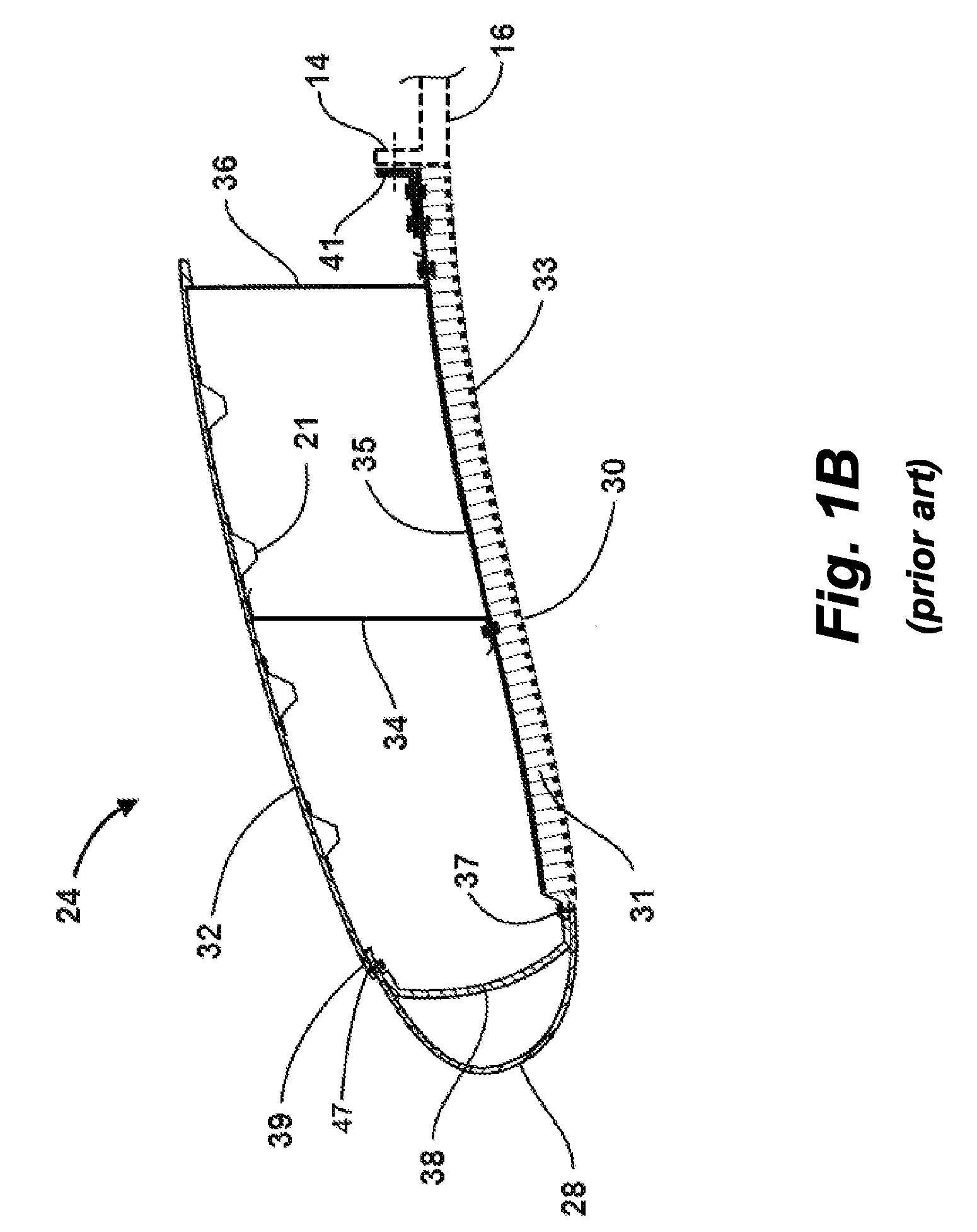
These loads can cause substantial damage to the nacelle inlet 24, including damage to an adjoined inner barrel 30.
Such loads can cause substantial deformation of a damaged inlet portion 24 and can result in unwanted aerodynamic drag.
Such loads also can cause cracks or breaks in a damaged composite inner barrel 30 to propagate, further compromising the structural integrity and stability of a damaged inlet portion 24 of a nacelle 22.

Method used


Image

  • Inlet section of an aircraft engine nacelle
  • Inlet section of an aircraft engine nacelle
  • Inlet section of an aircraft engine nacelle

Examples


second embodiment

[0033]A cross section of a nacelle inlet 300 according to the invention is shown in FIG. 3. In this embodiment, the nacelle inlet 300 includes an acoustically treated inner barrel 302, an outer shell 304, and an aft bulkhead 390. The outer shell 304 can include a nose lip portion 323 and an outer barrel portion 325. The nose lip portion 323 can include a trailing edge 306 that connects to a forward flange 316 on the inner barrel 302. The aft bulkhead 390 connects an aft portion of the outer shell 304 to a mounting flange 350. In one embodiment, the connection between the aft bulkhead 390 and the mounting flange 350 includes a plurality of circumferentially spaced rivets 397, or the like. As shown in FIG. 3, the aft bulkhead 390 can be connected to the aft edge of the outer barrel portion 325 of the outer shell 304 by a connecting ring 380 which can have a substantially T-shaped cross section. The aft bulkhead 390 and the outer barrel portion 325 can be connected to the connecting ri...

third embodiment

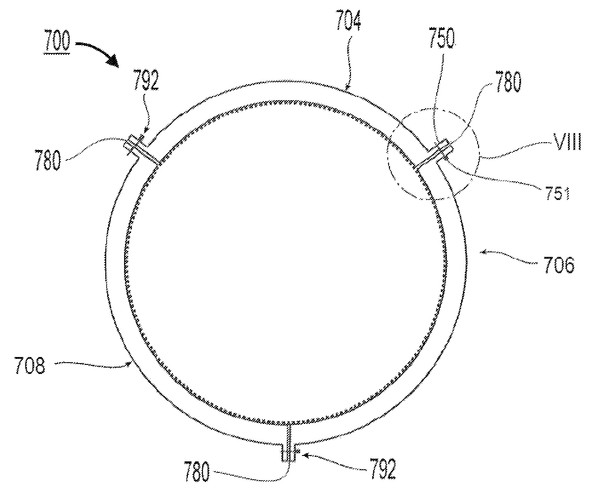
[0036]A cross section of a nacelle inlet 400 according to the invention is shown in FIG. 4. The nacelle inlet 400 can include an outer shell 404 and an aft bulkhead 490 that are substantially similar to the outer shell 304 and aft bulkhead 390 described above. In this embodiment, however, the mounting flange 491 is integrally formed as part of the composite outer skin 710 of the inner barrel 700. The aft bulkhead 490 can be connected to the integral mounting flange 491 by a bracket 492 and a plurality of fasteners 497, such as rivets, bolts, or the like. As shown in FIG. 4, a forward edge of the inner barrel 700 can be joined to an interior trailing edge 421 of the outer shell 404 by a substantially Z-shaped bracket 427 and pluralities of fasteners 402, such as rivets or the like. In the embodiment shown in FIG. 4, the inner barrel 700 can be constructed in a plurality of segments joined together along longitudinally extending flanges 750, for example. Alternatively, the inner barre...


PUM


Abstract

A nacelle inlet for an aircraft engine of a type having an engine fan case with a forward flange includes an acoustic inner barrel having a forward edge and an aft edge, an outer shell having a nose lip portion with a trailing inner edge, and an outer barrel portion having an aft portion. The nacelle inlet also includes an aft attachment flange configured to attach the inlet to the forward flange of the engine fan case, and an aft bulkhead having an aft end and connecting the outer barrel portion of the outer shell to the aft attachment flange. The forward edge of the acoustic inner barrel is connected to the trailing inner edge of the nose lip portion, and the aft portion of the inner barrel is attached to the aft attachment flange.

Description

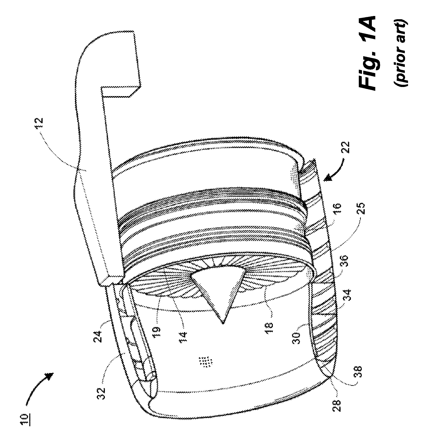
FIELD OF THE INVENTION[0001]The invention relates to nacelles for aircraft engines, and more particularly relates to an improved nacelle for a turbofan engine having an inlet cowl that is designed to assist in achieving a stable fly-home configuration subsequent to a blade-out event.BACKGROUND[0002]A nacelle for a turbofan engine must meet several basic design criteria. For example, the nacelle should direct air flow to the air intake of the engine while protecting the air flow from disturbances such as gusts, and the like. In addition, the exterior surface profile of the nacelle should minimize the aerodynamic drag caused by the engine and its related components.[0003]As shown in FIGS. 1A and 1B, a modern turbofan engine assembly 10 typically includes a nacelle 22 and a fan case 16. The engine assembly, including the nacelle 22 and fan case 16, can be suspended from an aircraft's wing by a pylon 12. In FIG. 1A, one side of the nacelle structure 22 is removed for ease of illustratio...

Claims


Application Information

Patent Timeline
IPC IPC(8): F01D25/24
CPCB64D29/08B64D33/02B64D29/06Y02B10/30Y02E10/726B64D2033/0206Y10T137/0536Y02E10/72
Inventor BINKS, ALANJAMES, NORMAN JOHNLAYLAND, MICHAEL JOHN
Owner ROHR INC
Learn More