Method and device for controlling an internal combustion engine

a technology of internal combustion engine and fuel-operated engine, which is applied in the direction of engine starters, electrical control, hose connections, etc., can solve the problems of internal combustion engine not being started, internal combustion engine sometimes not being restarted, and high concentration of fuel vapor in the intake, etc., to achieve reliable operation, rapid troubleshooting, and reliable overall operation of motor vehicles

Active Publication Date: 2010-10-21
ROBERT BOSCH GMBH
View PDF12 Cites 0 Cited by
  • Summary
  • Abstract
  • Description
  • Claims
  • Application Information

AI Technical Summary

Benefits of technology

[0008]The present invention has the advantage that after the internal combustion engine is shut off as determined by the shut-off strategy, a reliable start operation of the internal combustion engine is ensured. In particular, in known hybrid vehicles, which, in addition to an internal combustion engine also have an electric motor for propulsion, or in so-called start / stop controls of the internal combustion engine, the internal combustion engine is shut off as intended, during the operation of the vehicle. This takes place, for example, in idling of the internal combustion engine, while the vehicle is at a traffic light in a waiting phase. The present invention ensures a reliable restart of the internal combustion engine after such a shut-off. This has the following technical background:
[0011]The measures recited in the dependent claims make advantageous improvements on and refinements of the device described in the independent claim possible.
[0012]In one advantageous embodiment of the present invention, it is provided that at least one first state of the operating states represents a regular state of the tank venting system and at least one second state represents a defective state of the tank venting system. A regular state of the tank venting system may be present when a controller is capable of opening and closing the tank venting valve as desired. A defective state of the tank venting system may be present when a desired opening and closing of the tank venting valve is not possible. The shut-off strategy may ensure the reliable operation of the vehicle as a function of the instantaneous operating state.
[0013]In one further advantageous embodiment of the present invention it is provided that the tank venting system has at least one tank venting valve and / or one controller of the tank venting valve. In order to ensure reliable operation and rapid troubleshooting, it is convenient to consider the tank venting system as a system made up of a plurality of components. An extension of the monitoring function to individual components of the system makes it possible to adapt the shut-off strategy more specifically to the different operating states of the tank venting system.
[0015]In one further advantageous embodiment of the present invention it is provided that, in the case of a tank venting system recognized as defective, the shut-off strategy does not shut off the internal combustion engine or shuts it off with a delay. As mentioned previously, the start response of an internal combustion engine may be negatively affected as a result of a defective tank venting valve. Therefore, if a defective tank venting valve is recognized, the internal combustion engine is no longer shut off or is shut off much more restrictively in order to ensure reliable operation.
[0017]In one further advantageous embodiment of the present invention it is provided that, for determining the operating state of the tank venting system, a response of an engine controller is used, in particular a result of a tank leak diagnosis and / or a result of the idling control and / or lambda control by opening the tank venting valve. With the aid of these diagnostic options, a tank venting valve that is no longer able to close may be reliably recognized. The shut-off strategy may thus be reasonably adapted as needed.

Problems solved by technology

However, if the valve cannot be closed, the internal combustion engine sometimes cannot be restarted because the unclosed valve results in a high concentration of fuel vapors in the intake area of the internal combustion engine.
If this concentration exceeds a threshold value, the internal combustion engine may no longer be started, since the fuel / air mixture is too rich.

Method used


Image

  • Method and device for controlling an internal combustion engine
  • Method and device for controlling an internal combustion engine
  • Method and device for controlling an internal combustion engine

Examples


Embodiment Construction

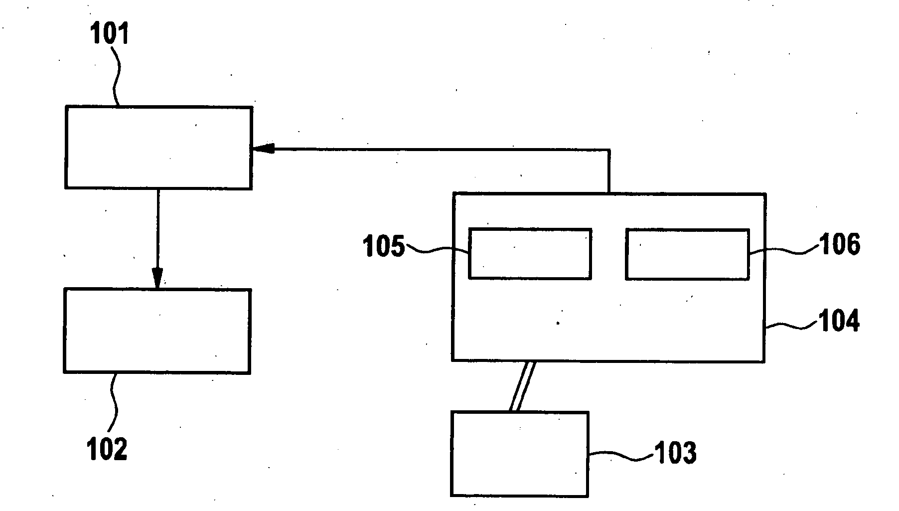
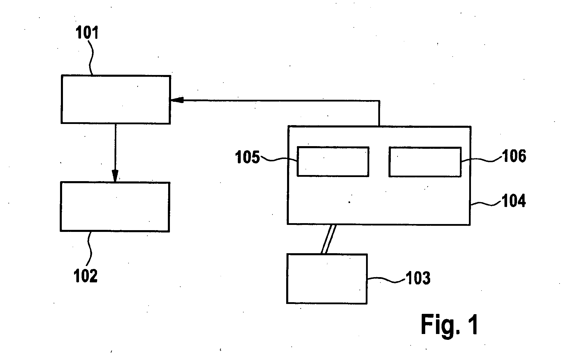
[0020]FIG. 1 shows a device for controlling an internal combustion engine. An internal combustion engine (102) is controlled using means (101). A fuel tank (103), which is equipped with a tank venting system (104), is associated with the internal combustion engine. The tank venting system (104) has the tank venting valve (105) and the controller (106) for the tank venting valve (105). The operating state of the tank venting system is transmitted to the means (101) as an input variable.

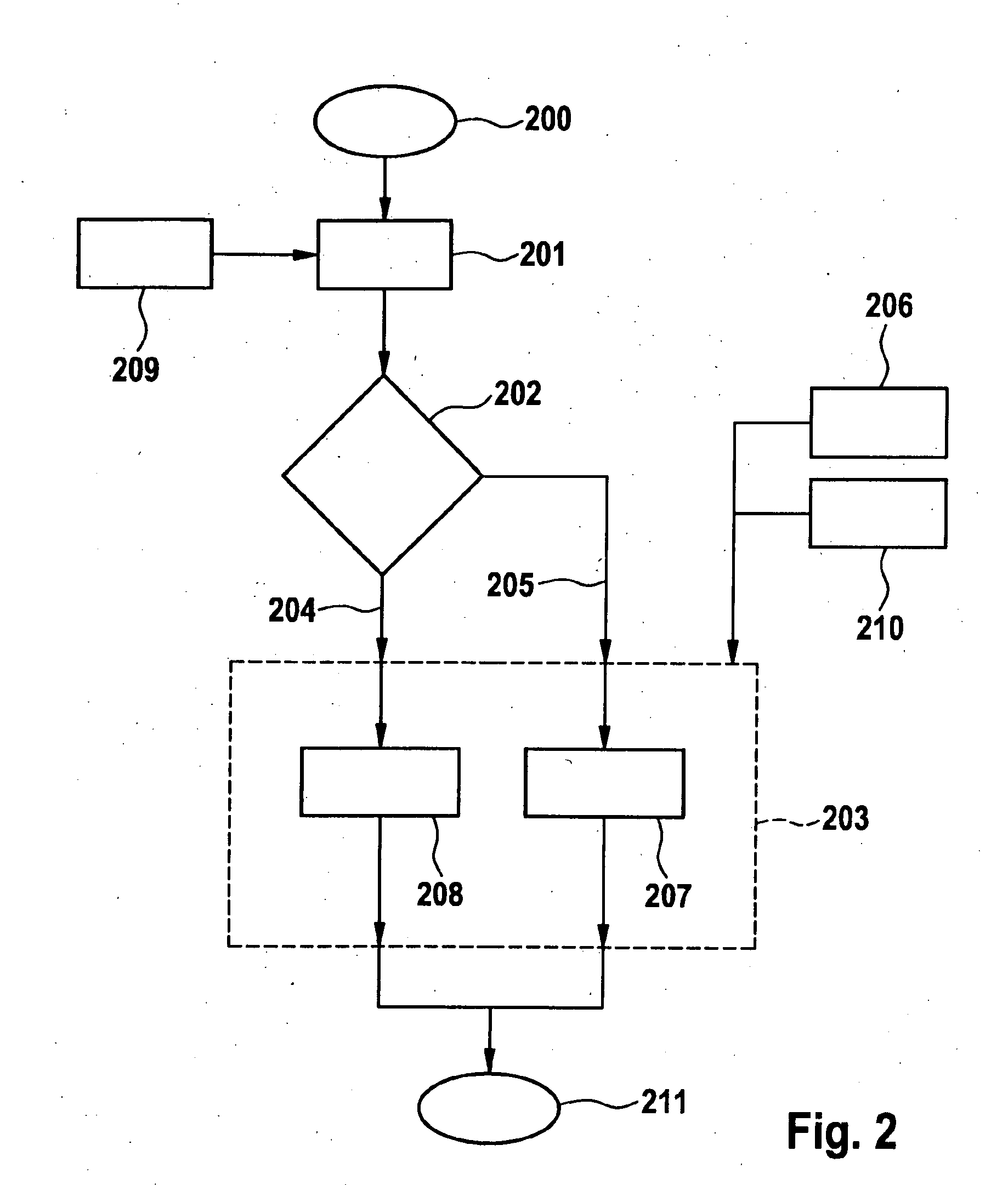
[0021]FIG. 2 shows a method for controlling an internal combustion engine.

[0022]Block (200) identifies the start of the method; block (211) identifies the end of the method. The operating state of the tank venting system is diagnosed in block (209).

[0023]As mentioned previously, a tank leak diagnosis may be performed and evaluated for determining the operating state of the tank venting system. However, the operating state of the tank venting system may also be inferred from the control response of the ...


PUM


Abstract

A method and a device for controlling a fuel-operated internal combustion engine of a motor vehicle having a tank venting system associated with a fuel tank and having at least two operating states, in which the internal combustion engine is shut off automatically according to a shut-off strategy. The shut-off strategy takes into account the instantaneous operating state of the tank venting system.

Description

BACKGROUND OF THE INVENTION[0001]1. FIELD OF THE INVENTION[0002]The present invention is directed to a method and a device for controlling a fuel-operated internal combustion engine of a motor vehicle.[0003]2. DESCRIPTION OF RELATED ART[0004]A fuel tank is normally present in motor vehicles for storing the fuel. The fuel tank is equipped with a tank venting system. The tank venting system is used for sealing the tank to prevent fuel or fuel vapors from escaping from the tank in an uncontrolled manner. With the help of a controllable tank venting system, a tank venting valve may be opened and the pressure may be modified in a controlled manner.[0005]U.S. Pat. No. 5,371,412 describes a hybrid vehicle in which an internal combustion engine is started or shut off as a function of the load of the active carbon filter in the tank venting system.SUMMARY OF THE INVENTION[0006]The present invention is directed to a method and a device for controlling a fuel-operated internal combustion engin...

Claims


Application Information

Patent Timeline
Patent Type & Authority Applications(United States)
IPC IPC(8): F17D1/00F16L35/00
CPCF02D41/003F02D41/042Y02T10/48F02N11/0825F02M25/0827Y02T10/40Y10T137/0318Y10T137/9247
Inventor ZELL, HELMUTPAPE, ANDREAS
Owner ROBERT BOSCH GMBH
Why Eureka
Try Eureka