Counter-rotational inertial control of rotorcraft

a technology of counter-rotational rotors and inertial control, which is applied in the direction of liquid fuel engines, vessel construction, marine propulsion, etc., can solve the problems of unbalance torque, increased pitch, and limited development of this type of aircra

Inactive Publication Date: 2010-10-21
THE TRUSTEES OF THE UNIV OF PENNSYLVANIA
View PDF14 Cites 36 Cited by
  • Summary
  • Abstract
  • Description
  • Claims
  • Application Information

AI Technical Summary

Problems solved by technology

However, because of difficulties involved in the control of cyclic and collective pitch of rotor blades in a coaxial configuration, development of this type of aircraft has heretofore been limited.
Pitch is increased in one rotor, and decreased in the other, to unbalance torque.
Common to these is that a yaw attitude control input is provided by enabling a different blade pitch magnitude for the first rotor as compared to the second rotor, thereby unbalancing the torque forces in the coaxial rotor set.

Method used


Image

  • Counter-rotational inertial control of rotorcraft
  • Counter-rotational inertial control of rotorcraft
  • Counter-rotational inertial control of rotorcraft

Examples


Embodiment Construction

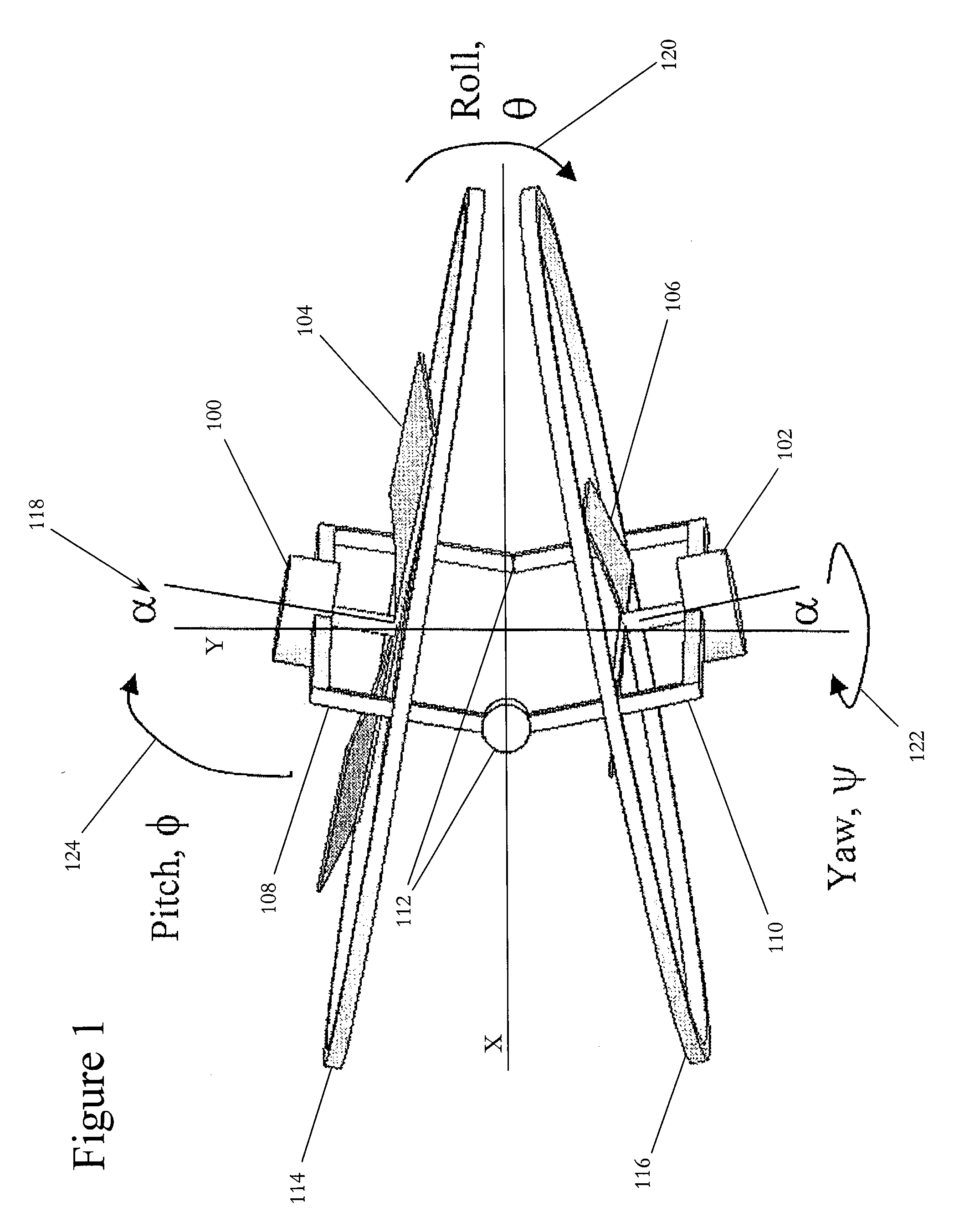
[0019]The exemplary embodiments of the present invention use inertia, rather than aerodynamics, to control the pitch and roll of a rotorcraft. Suitable rotorcraft for use with the present invention include, for example, vertical take-off and landing (VTOL) aircrafts. This approach simplifies the construction of exemplary rotorcraft that do not have complex interactions between various rotating components. Additionally, this approach enables larger and faster control authority over the attitude of the rotorcraft. Exemplary methods of inertial attitude control according to the present invention result in a simplified control model for rotorcraft. The examples of inertial control described herein may rely on gyroscopic control to command a rotorcraft. This simplified control model may allow for improved control of rotorcraft by either human pilots or automated flight control systems.

[0020]FIG. 1 illustrates an exemplary rotorcraft according to the present invention. This exemplary roto...


PUM


Abstract

A rotorcraft with two counter-rotating rotors and method for inertially controlling the rotorcraft. The rotorcraft includes a hinged frame configured such that at least one inter-rotor angle of the two counter-rotating rotors is controlled by at least one actuated hinge of the hinged frame and the rotational axes of the two counter-rotating rotors are substantially collinear when the actuated hinge is in a fully open position. The sum of the magnitudes of torque applied to the two counter-rotating rotors is varied to control the lift of the rotorcraft. The difference of the magnitudes of torque applied to the two counter-rotating rotors is varied to control the yaw of the rotorcraft. The at least one inter-rotor angle is varied using the at least one actuated hinge to control the pitch and / or roll of the rotorcraft.

Description

FIELD OF THE INVENTION[0001]The present invention concerns rotorcraft with counter-rotating rotors and inertial control of such rotorcraft. In particular, these methods may be used for improved performance, simplified control, and simplified manufacture of these rotorcraft.BACKGROUND OF THE INVENTION[0002]Coaxial rotorcraft have been known for many years. However, because of difficulties involved in the control of cyclic and collective pitch of rotor blades in a coaxial configuration, development of this type of aircraft has heretofore been limited. Conventional coaxial designs provide roll, pitch and yaw control by providing control input linkages for cyclic and collective pitch to both an upper rotor and a lower rotor of a coaxial rotor set. This has conventionally involved providing at least two swash plates. One below, and one above, the lower rotor, to transfer control inputs past the lower rotor to the upper rotor, which is rotating in the opposite direction.[0003]Several succ...

Claims


Application Information

Patent Timeline
Patent Type & Authority Applications(United States)
IPC IPC(8): B64C27/08B63H5/08
CPCB64C27/20B64C29/0033B64C27/52
Inventor YIM, MARKTHORNE, CHRISTOPHER EVERETT
Owner THE TRUSTEES OF THE UNIV OF PENNSYLVANIA
Why Eureka
Try Eureka