Insulator structure of motor, and motor-integrated pump

a technology of integrated pump and insulation structure, which is applied in the direction of windings, electrical devices, dynamo-electric machines, etc., can solve the problems of increasing cost and achieve the effect of decreasing production costs

Inactive Publication Date: 2010-10-21
PANASONIC CORP
View PDF8 Cites 12 Cited by
  • Summary
  • Abstract
  • Description
  • Claims
  • Application Information

AI Technical Summary

Benefits of technology

[0007]In view of the above problem, it is an object of the present invention to provide a motor's insulator structure capable of decreasing production cost by using the same configuration for each of a pair of insulators.

Problems solved by technology

According to the patent literature 1, however, the two insulators having different configurations in a portion where the cover portions are superposed with each other and thereby are produced as different parts, thus causing an increased cost.

Method used


Image

  • Insulator structure of motor, and motor-integrated pump
  • Insulator structure of motor, and motor-integrated pump
  • Insulator structure of motor, and motor-integrated pump

Examples


first embodiment

(Modified Examples of First Embodiment)

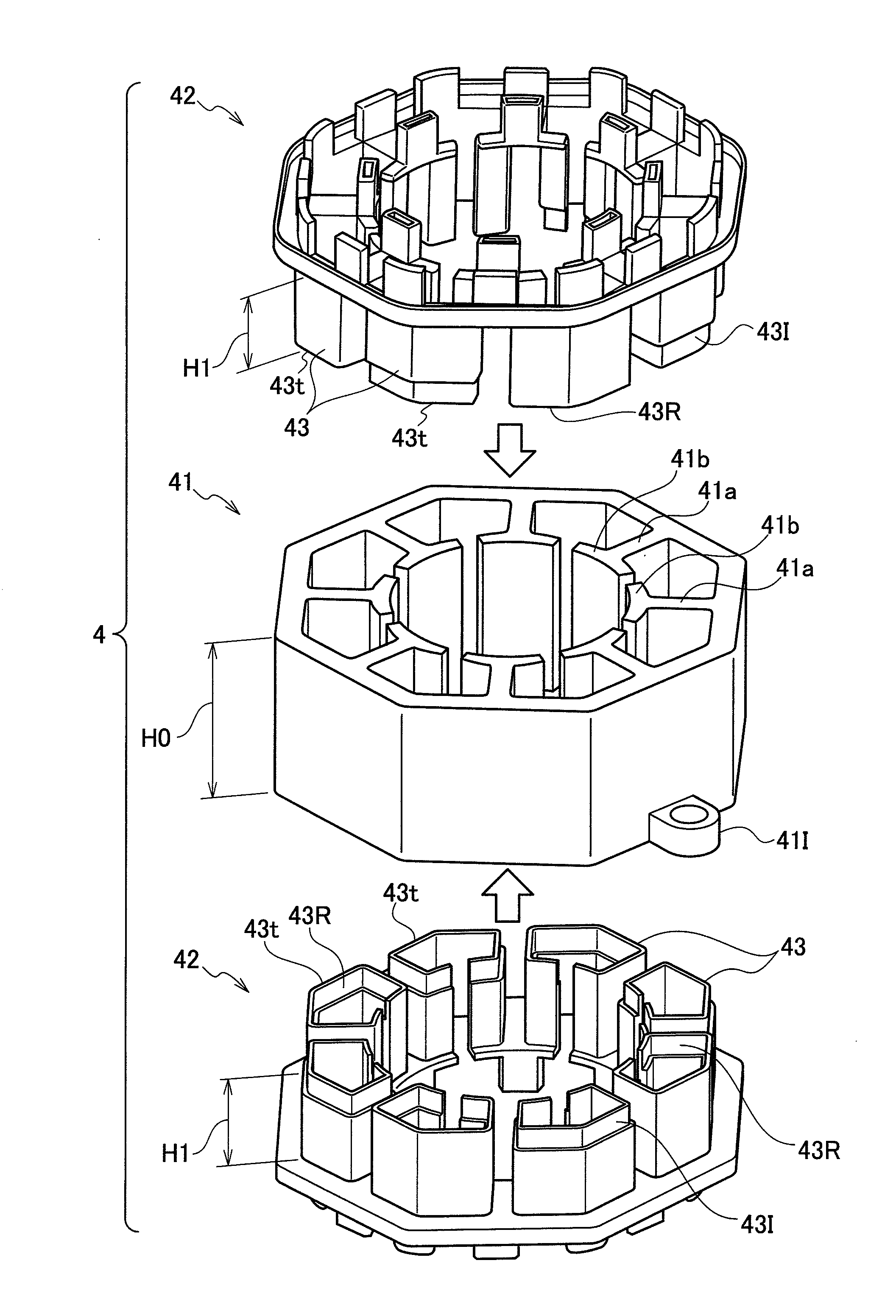
[0043]FIG. 8 is a perspective view showing the cover portion 43 side of an insulator 42-1 according to a first modified example of the first embodiment, while FIG. 9 is a perspective view showing the cover portion 43 side of an insulator 42-2 according to a second modified example of the first embodiment.

[0044]The insulator 42-1 shown in FIG. 8 and the insulator 42-2 shown in FIG. 9 have such a structure that first cover portion groups 50A1 (including the first fitting portion 43I), 50A2 (including the first fitting portion 43I) including a plurality of cover portions 43 having the first fitting portion 43I and second cover portion groups 50B1 (including the second fitting portion 43R), 50B2 (including the second fitting portion 43R) fittable with the first cover portion groups 50A1, 50A2 are alternately disposed at certain pitches along the circumferential direction of the center axis 41C.

[0045]With the insulator 42-1 shown in FIG. 8, the firs...

second embodiment

[0051]FIG. 10 is a perspective view of an insulator 42A, according to a second embodiment of the present invention.

[0052]The second embodiment is different from the first embodiment in that the second embodiment has such a structure that alignment marks 49A, 49B each serving as a guidepost for indicating position of mounting the insulator 42A to the stator core 41 are disposed at the insulator 42A.

[0053]Specifically, on the insulator 42A's side opposite to the insulator 42A's side provided with the cover portion 43, the alignment marks 49A, 49B are provided as protruding portions P1, P2 which protrude corresponding to the respective cover portions 43. Then, a height h1 of the protruding portion P1 corresponding to the cover portion 43 provided with the first fitting portion 43I and a height h2 of the protruding portion P2 corresponding to the cover portion 43 provided with the second fitting portion 43R are made different (h1>h2) from each other, to thereby accomplish a distinction ...


PUM


Abstract

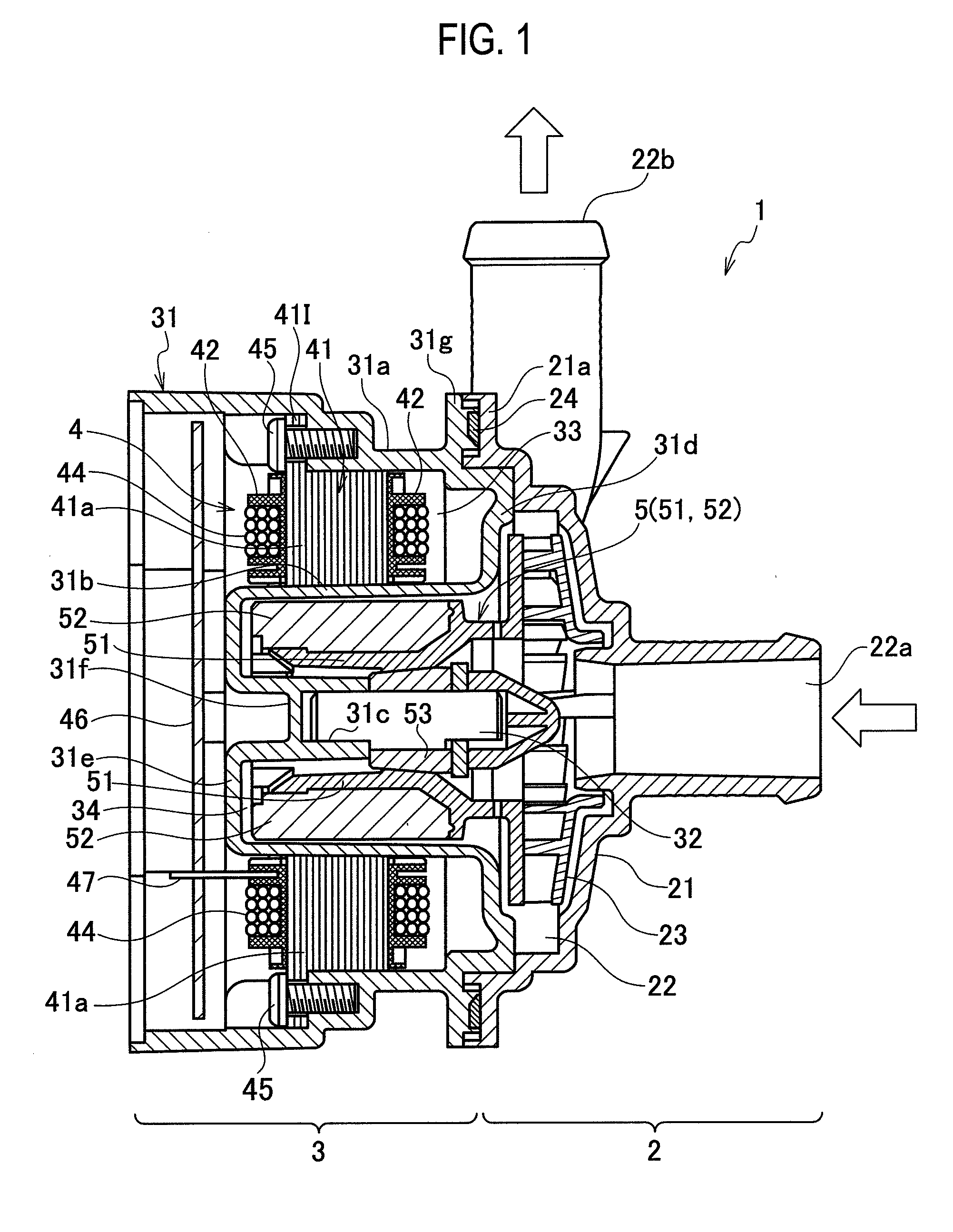
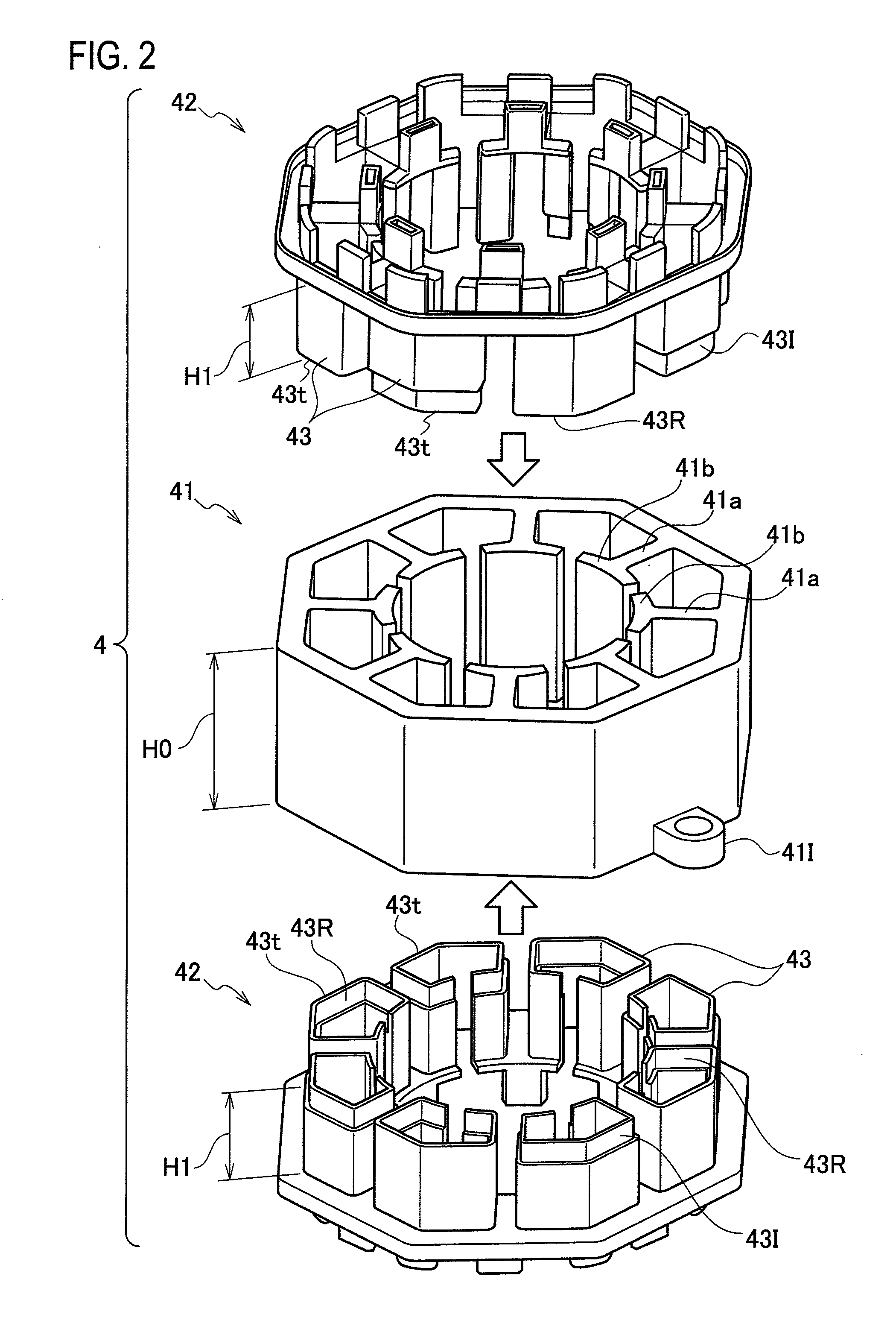
An insulator structure of a motor, includes: a stator core having a plurality of protruding tooth portions which are disposed along an inner periphery of the stator core or an outer periphery of the stator core; a pair of first and second insulators respectively mounted to a first end portion and a second end portion in an axial direction of the stator core, wherein a plurality of cover portions are provided for each of the pair of the first and second insulators so as to cover the plurality of the respective tooth portions; and a winding wound around a tooth portion of the tooth portions covered with the respective cover portions, the winding being capable of causing a magnetic force to the tooth portion by an energizing; wherein with the pair of the first and second insulators, the cover portion's second head end portion in an axial direction of the first insulator in the axial direction and the cover portion's first head end portion in an axial direction of the second insulator in the axial direction mate with each other, the cover portion having the head end portion in the axial direction provided with a first fitting portion and the cover portion having the head end portion in the axial direction provided with a second fitting portion fittable with the first fitting portion are provided for each of the pair of the first and second insulators, the cover portion provided with the first fitting portion and the cover portion provided with the second fitting portion are so disposed as to face each other in such a configuration as to interpose therebetween a center axis of the stator core, and the first insulator and the second insulator which is substantially the same as the first insulator in configuration and is reversed in the axial direction are configured to face each other, such that the first fitting portion of the first insulator mates with the second fitting portion of the second insulator.

Description

TECHNICAL FIELD[0001]The present invention relates to an insulator structure of a motor and also relates to a motor-integrated pump.[0002]Patent literature 1 discloses a conventional motor provided with a stator core having a plurality of stacked stator iron plates and a plurality of tooth portions provided on an inner periphery of the stator core and arranged at regular intervals in the circumferential direction.[0003]According to the patent literature 1, insulators are provided at both end portions in an axial direction of the center axis of the stator core, and a plurality of cover portions for covering the outside of the tooth portions are provided at regular intervals in the circumferential direction. Then, a winding is wound around the tooth portion covered with the cover portion. Namely, the cover portions (insulator) assuredly insulate the tooth portion (stator core) from the winding while a magnetic force can be caused to the tooth portions by energizing the winding.[0004]I...

Claims


Application Information

Patent Timeline
Patent Type & Authority Applications(United States)
IPC IPC(8): H02K3/34
CPCH02K2203/12H02K3/522
Inventor TOKUNAGA, RYOHEI
Owner PANASONIC CORP
Why Eureka
Try Eureka