System and method for phase relaxed RF pulse design

a phase relaxation and pulse design technology, applied in the field of magnetic resonance imaging systems, can solve the problems of inaccurate design, over-constrained, and unoptimized magnitude profiles

Active Publication Date: 2010-10-21
GENERAL ELECTRIC CO
View PDF5 Cites 13 Cited by
  • Summary
  • Abstract
  • Description
  • Claims
  • Application Information

AI Technical Summary

Benefits of technology

[0010]In accordance with an embodiment, a method for magnetic resonance (MR) imaging includes determining at least one RF pulse profile, identifying a set of desired magnetization parameters, iteratively adjusting the at least one RF pulse profile based on the set of desired magnetization parameters using a spinor-based, phase relaxed, optimal control formulation and causing an RF coil array to transmit at least one RF pulse based on the at least one adjusted RF pulse profile to acquire MR imaging data.
[0011]In accordance with another embodiment, a magnetic resonance (MR) imaging apparatus includes a plurality of gradient coils positioned about a bore of a magnet, an RF transceiv

Problems solved by technology

This is overly constrained because a parallel transmission array does not necessarily favor excitation with flat phase.
Conventional STA parallel transmission designs can have the following limitation

Method used


Image

  • System and method for phase relaxed RF pulse design
  • System and method for phase relaxed RF pulse design
  • System and method for phase relaxed RF pulse design

Examples


Embodiment Construction

[0019]In the following detailed description, numerous specific details are set forth in order to provide a thorough understanding of embodiments. However it will be understood by those of ordinary skill in the art that the embodiments may be practiced without these specific details. In other instances, well-known methods, procedures, components and circuits have not been described in detail so as not to obscure the embodiments.

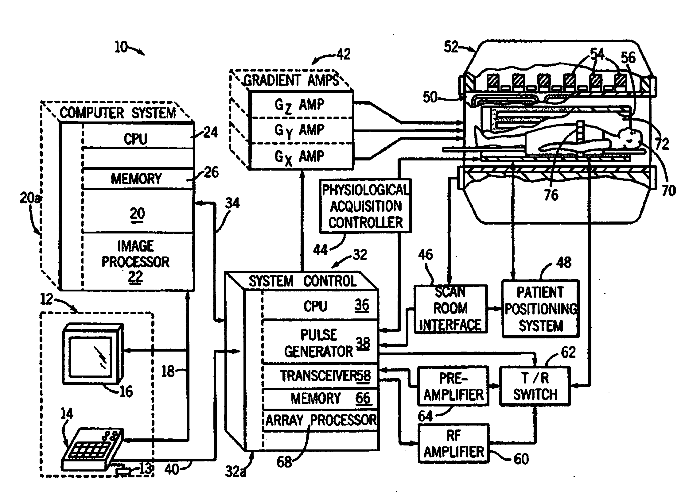
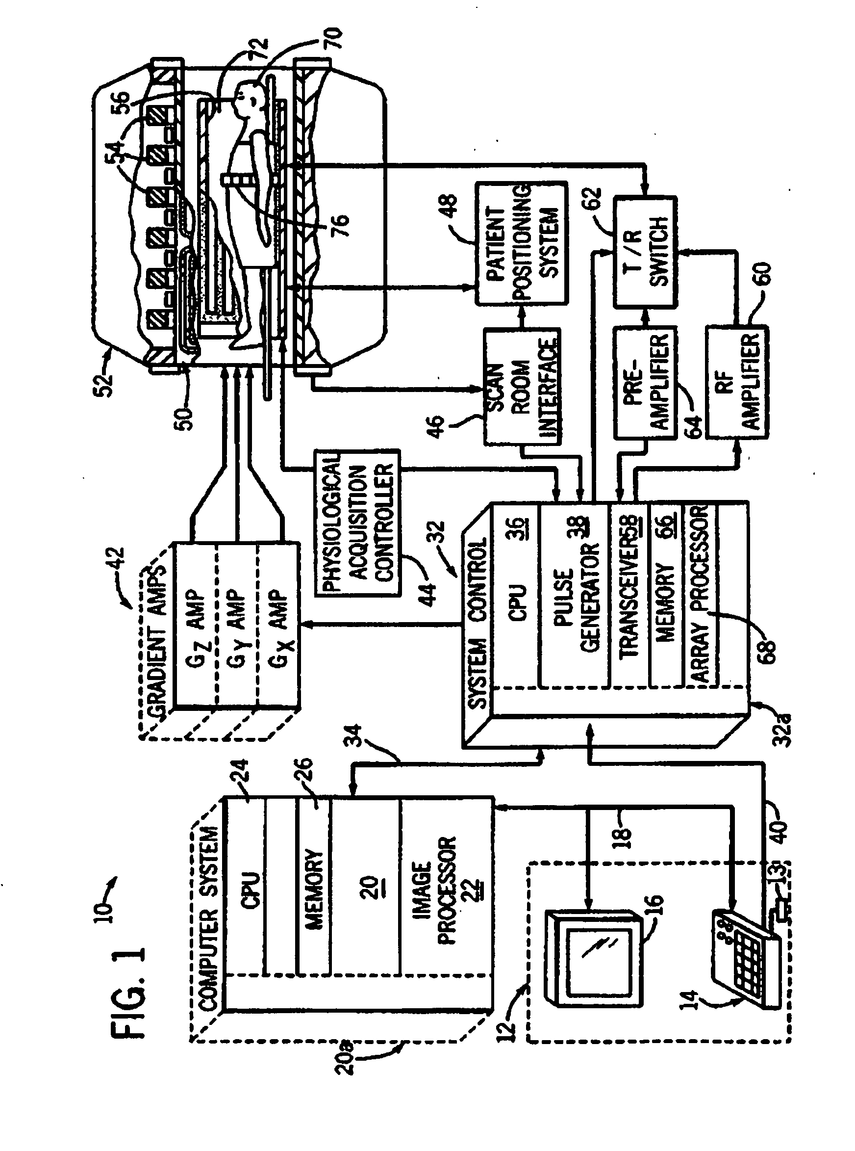
[0020]FIG. 1 is a schematic block diagram of an exemplary magnetic resonance imaging system in accordance with an embodiment. The operation of MRI system 10 is controlled from an operator console 12 that includes a keyboard or other input device 13, a control panel 14 and a display 16. The console 12 communicates through a link 18 with a computer system 20 and provides an interface for an operator to prescribe MRI scans, display the resultant images, perform image processing on the images, and archive data and images. The computer system 20 includes a number o...


PUM


Abstract

Techniques for designing RF pulses may be configured to produce improved magnitude profiles of the resulting magnetization by relaxing the phase constraint and optimizing the phase profiles. In one embodiment, a spinor-based, optimal control, optimal phase technique may be used to design arbitrary-tip-angle (e.g., large and small tip angle) RF pulses (both parallel transmission and single channel). In another embodiment, small tip angle RF pulses (both parallel transmission and single channel) may be designed using a small-tip-angle (STA) pulse design without phase constraint that is formulated as a parameter optimization problem.

Description

TECHNICAL FIELD[0001]The present invention relates generally to magnetic resonance imaging (MRI) systems and in particular, to a system and method for phase relaxed RF pulse design.BACKGROUND[0002]Magnetic resonance imaging (MRI) is a medical imaging modality that can create images of the inside of a human body without using x-rays or other ionizing radiation. MRI uses a powerful magnet to create a strong, uniform, static magnetic field (i.e., the “main magnetic field”). When a human body, or part of a human body, is placed in the main magnetic field, the nuclear spins that are associated with the hydrogen nuclei in tissue water become polarized. This means that the magnetic moments that are associated with these spins become preferentially aligned along the direction of the main magnetic field, resulting in a small net tissue magnetization along that axis (the “z axis,” by convention). A MRI system also comprises components called gradient coils that produce smaller amplitude, spat...

Claims


Application Information

Patent Timeline
IPC IPC(8): G01R33/20
CPCG01R33/5612
Inventor XU, DANKING, KEVIN F.MCKINNON, GRAEME C.
Owner GENERAL ELECTRIC CO
Why Eureka
Try Eureka