

Information processing device
- Summary
- Abstract
- Description
- Claims
- Application Information
AI Technical Summary
Benefits of technology
Problems solved by technology
Method used
Image

Examples
first embodiment
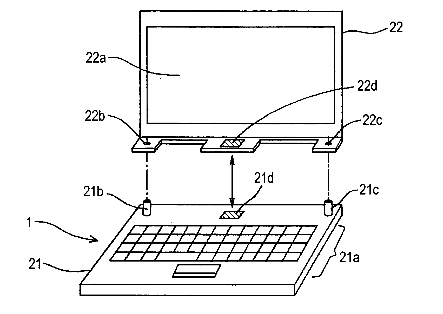
[0053]FIG. 1 shows an appearance example of a single unit computer 1 seen from the front according to a first embodiment.
[0054]The single unit personal computer (referred to as a single unit PC in the following description) includes a body 21 and a display portion 22 attachable to and detachable from the body 21.
[0055]The body 21 supplies a video signal to the display portion 22 by a close-range high speed wireless communication while mounting (supporting) the display portion 22 to display an image corresponding to the video signal.
[0056]Here, the close-range high speed wireless communication is wireless communication performed between the body 21 and the display portion 22, which is the wireless communication in which a wireless signal is exchanged between the body 21 and the display portion 22 which are in close proximity to each other to a degree that the signal is not received by communication devices other than the body 21 and the display portion 22.
[0057]In the close-range hig...
second embodiment
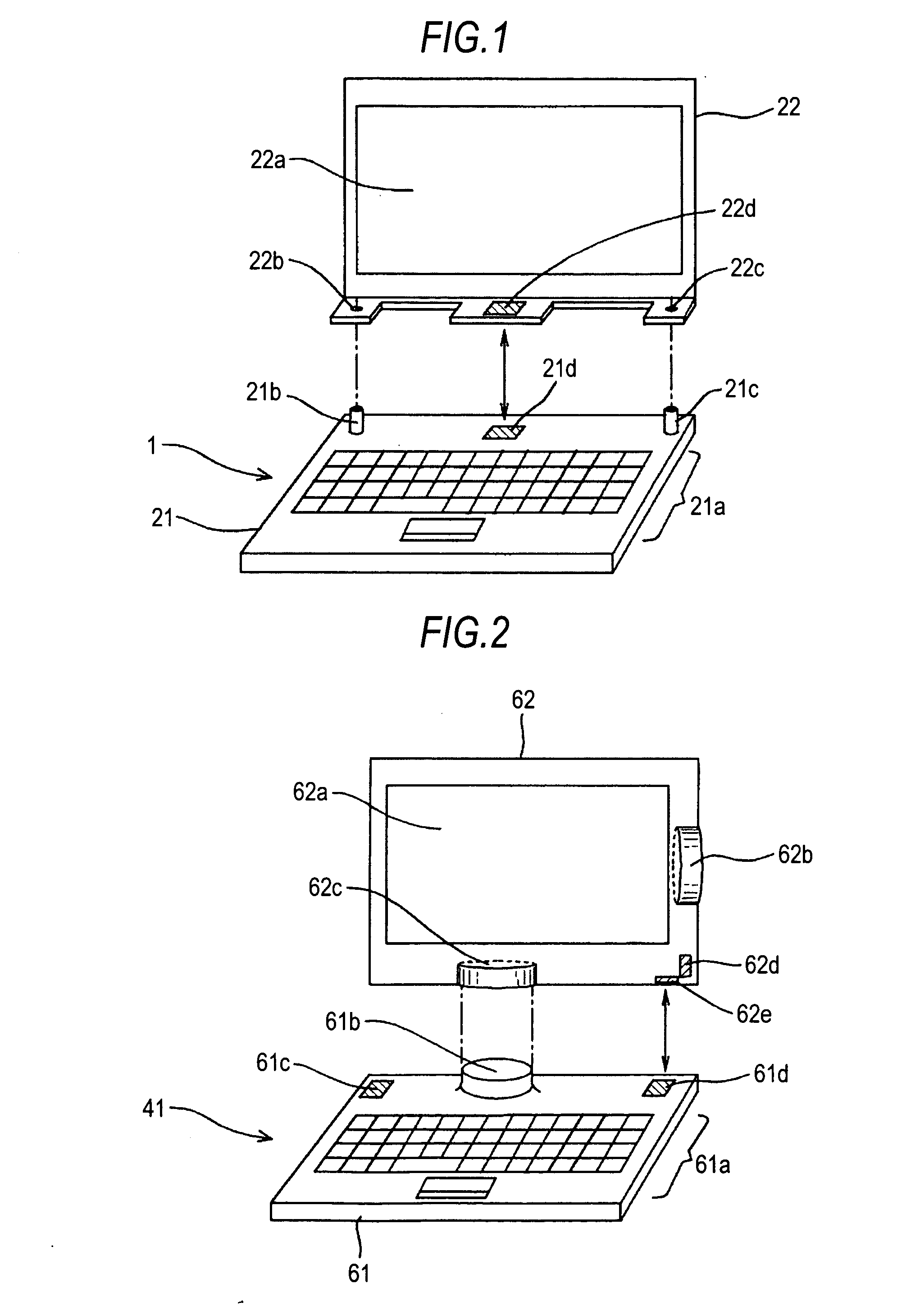
[0073]Next, a single unit PC 41 according to a second embodiment will be explained with reference to FIG. 2 and FIG. 3.
[0074]FIG. 2 and FIG. 3 show appearance examples of the single unit PC 41 seen from the front according to the second embodiment.
[0075]The single unit PC 41 includes a body 61 and a display portion 62 attachable to and detachable from the body 61 in landscape orientation or in portrait orientation.
[0076]The body 61 supplies a video signal to the display portion 62 by a close-range high speed wireless communication while supporting the display portion 62 to display an image corresponding to the video signal.
[0077]The body 61 is provided with, in addition to an operation portion 21a such as a keyboard and a touch pad, a convex portion 61b used for supporting the display portion 62 and couplers 61c, 61d formed in the same manner as the coupler 21d of FIG. 1.
[0078]The display portion 62 has an approximately rectangular parallelepiped shape.
[0079]The display portion 62 i...
third embodiment
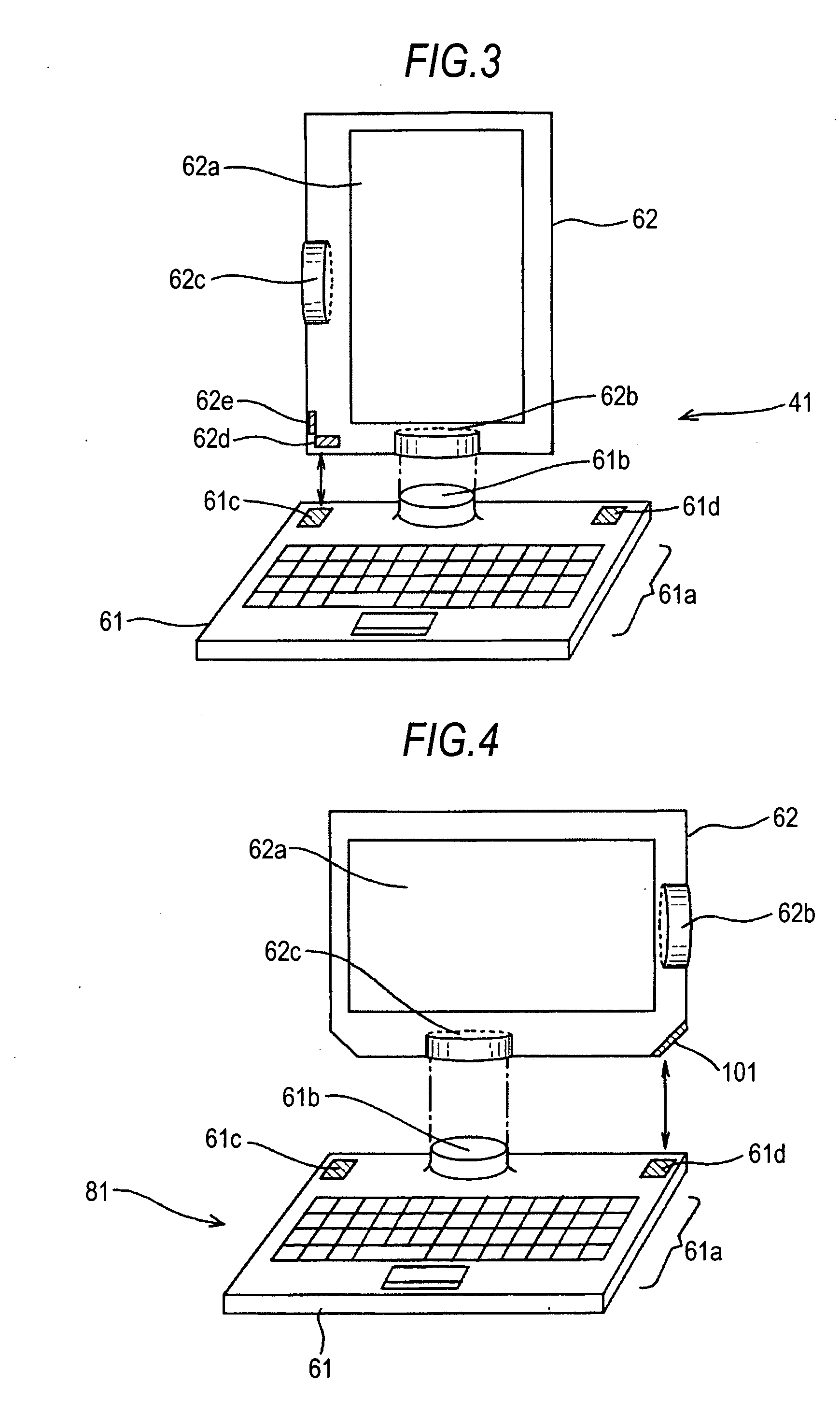
[0090]Next, a single unit PC 81 according to a third embodiment which includes one coupler 101 instead of two couplers 62d and 62e will be explained with reference to FIG. 4 and FIG. 5.
[0091]FIG. 4 and FIG. 5 show appearance examples of the single unit PC 81 seen from the front according to the third embodiment.
[0092]In the single unit PC 81, the same signs are given to components formed in the same manner as the single unit PC 41 according to the second embodiment, therefore, explanation thereof will be omitted below.
[0093]That is, the single unit PC 81 is formed in the same manner as the single unit PC 41 except that the coupler 101 is provided instead of the coupler 62d and coupler 62e in the display portion 62.
[0094]In the display portion 62, the coupler 101 is provided obliquely at a corner portion of the lower right direction of the display portion 62 in FIG. 4 so that an angle with respect to the horizontal direction of FIG. 4 is 45 degrees.
[0095]When the convex portion 61b o...
PUM
 Abstract
Description
Claims
Application Information