Locking assembly for locking an electronics card to a rack
- Summary
- Abstract
- Description
- Claims
- Application Information
AI Technical Summary
Benefits of technology
Problems solved by technology
Method used
Image
Examples
Embodiment Construction
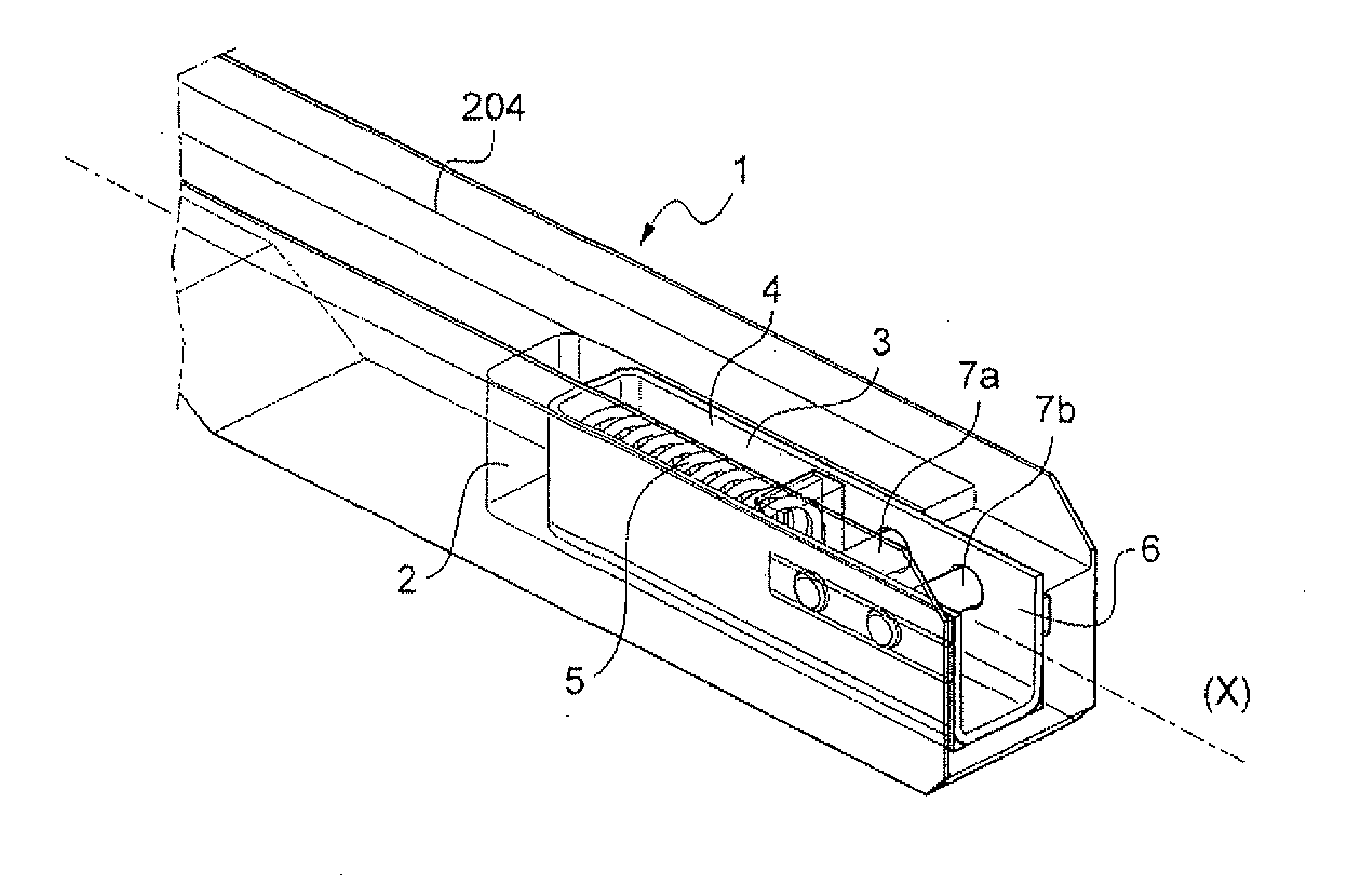
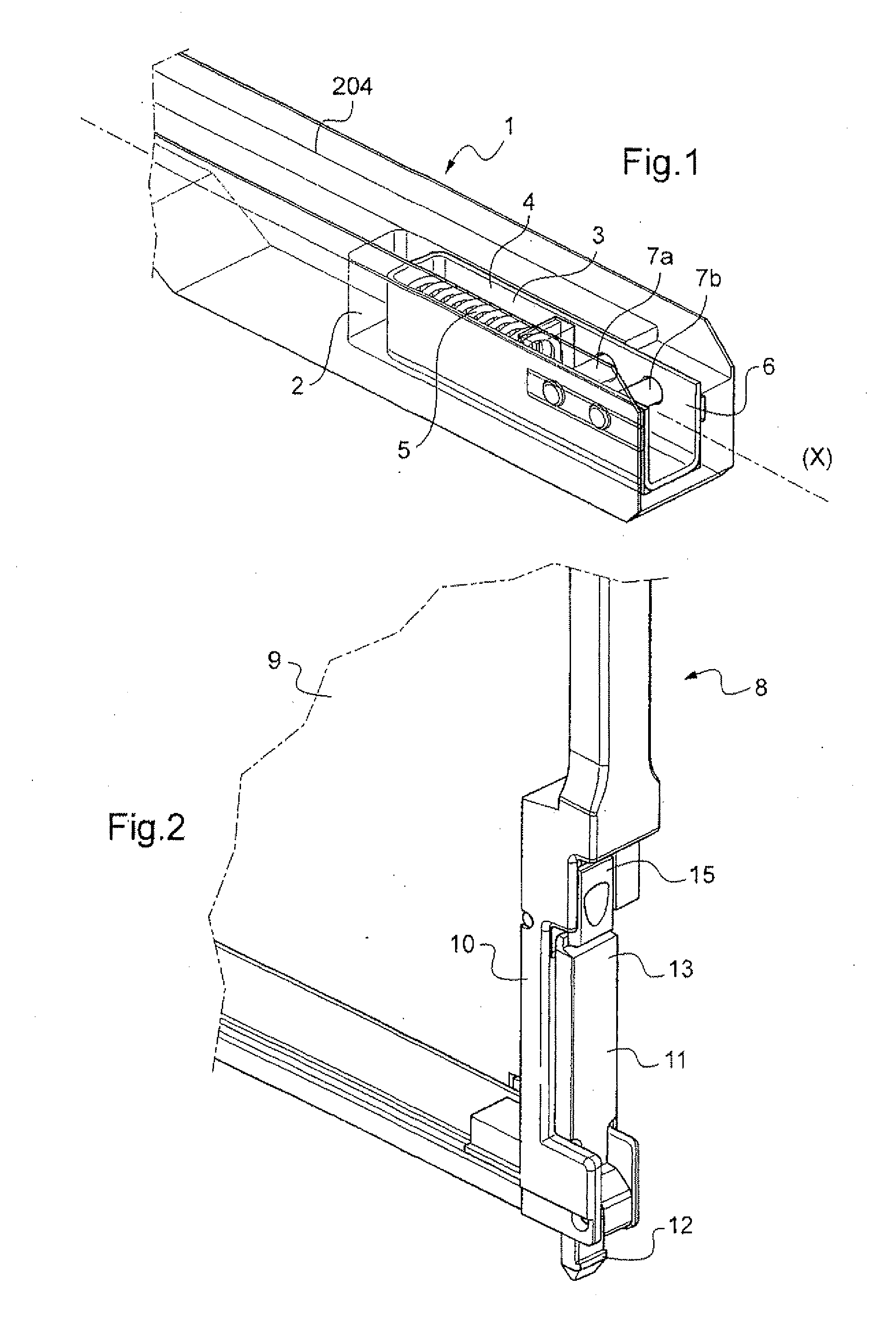
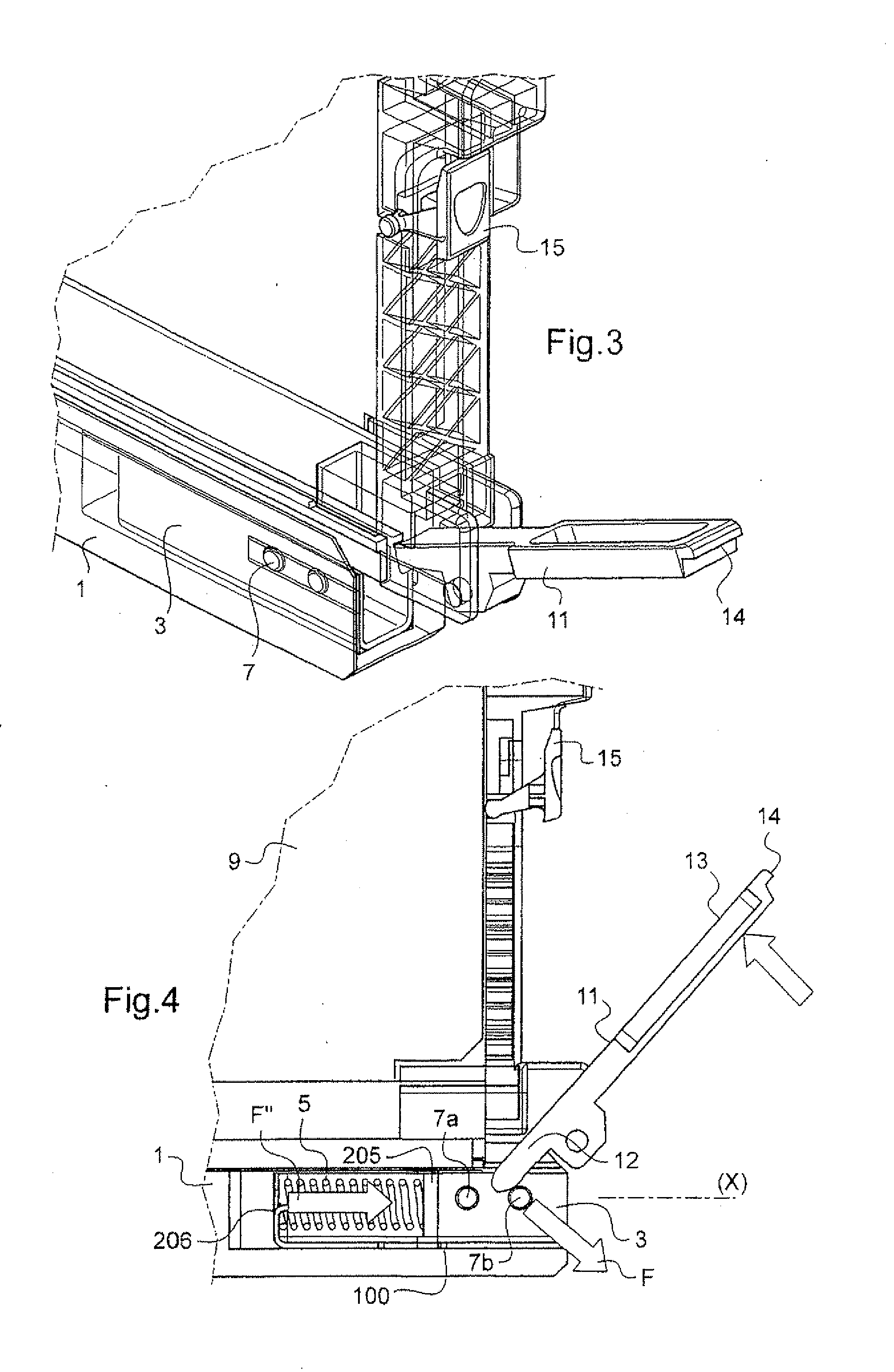
[0086]First embodiments of a locking assembly are described with reference to FIGS. 1 to 7.
[0087]This assembly comprises a rack given overall reference 1 and an electronics card given overall reference 8.
[0088]FIG. 17 is a diagram of a conventional rack 1. That rack comprises an open front face 200, side cheeks 201, a back plate 202, a top plate 203, and a bottom plate 204. As shown in FIG. 1, a housing 2 is formed inside the bottom plate 204 of the rack 1. A carriage 3 extending along a longitudinal axis X is received in the housing 2 so as to be movable in the housing along the axis X. By way of example, the carriage 3 is made of plastics material or of metal, e.g. being obtained by molding, machining, or cutting and folding.
[0089]In the example described the housing 2 is formed in the bottom plate of the rack close to the entry zone for an electronics card into the rack 1, however the invention is not limited to such an example.
[0090]The carriage 3 has a front portion 4 defining ...
PUM
 Abstract
Description
Claims
Application Information
 - R&D
- Intellectual Property
- Life Sciences
- Materials
- Tech Scout
- Unparalleled Data Quality
- Higher Quality Content
- 60% Fewer Hallucinations
Browse by: Latest US Patents, China's latest patents, Technical Efficacy Thesaurus, Application Domain, Technology Topic, Popular Technical Reports.
© 2025 PatSnap. All rights reserved.Legal|Privacy policy|Modern Slavery Act Transparency Statement|Sitemap|About US| Contact US: help@patsnap.com


