Rotary disk crop harvesting header with an auger for transferring the crop

a technology of crop harvesting and headers, which is applied in the field of rotary disk crop harvesting headers with, can solve the problems of ineffective supply of a required width, no other feed devices such as drums,

Active Publication Date: 2010-10-28
MACDON INDS
View PDF24 Cites 27 Cited by
  • Summary
  • Abstract
  • Description
  • Claims
  • Application Information

AI Technical Summary

Problems solved by technology

No other feed devices such as drums are use in conjunction with the overshot auger.
This arrangement is designed for an 8 or 10 disk machine but is ineffective at providing a properly consolidated swath of a required width.

Method used


Image

  • Rotary disk crop harvesting header with an auger for transferring the crop
  • Rotary disk crop harvesting header with an auger for transferring the crop
  • Rotary disk crop harvesting header with an auger for transferring the crop

Examples


Embodiment Construction

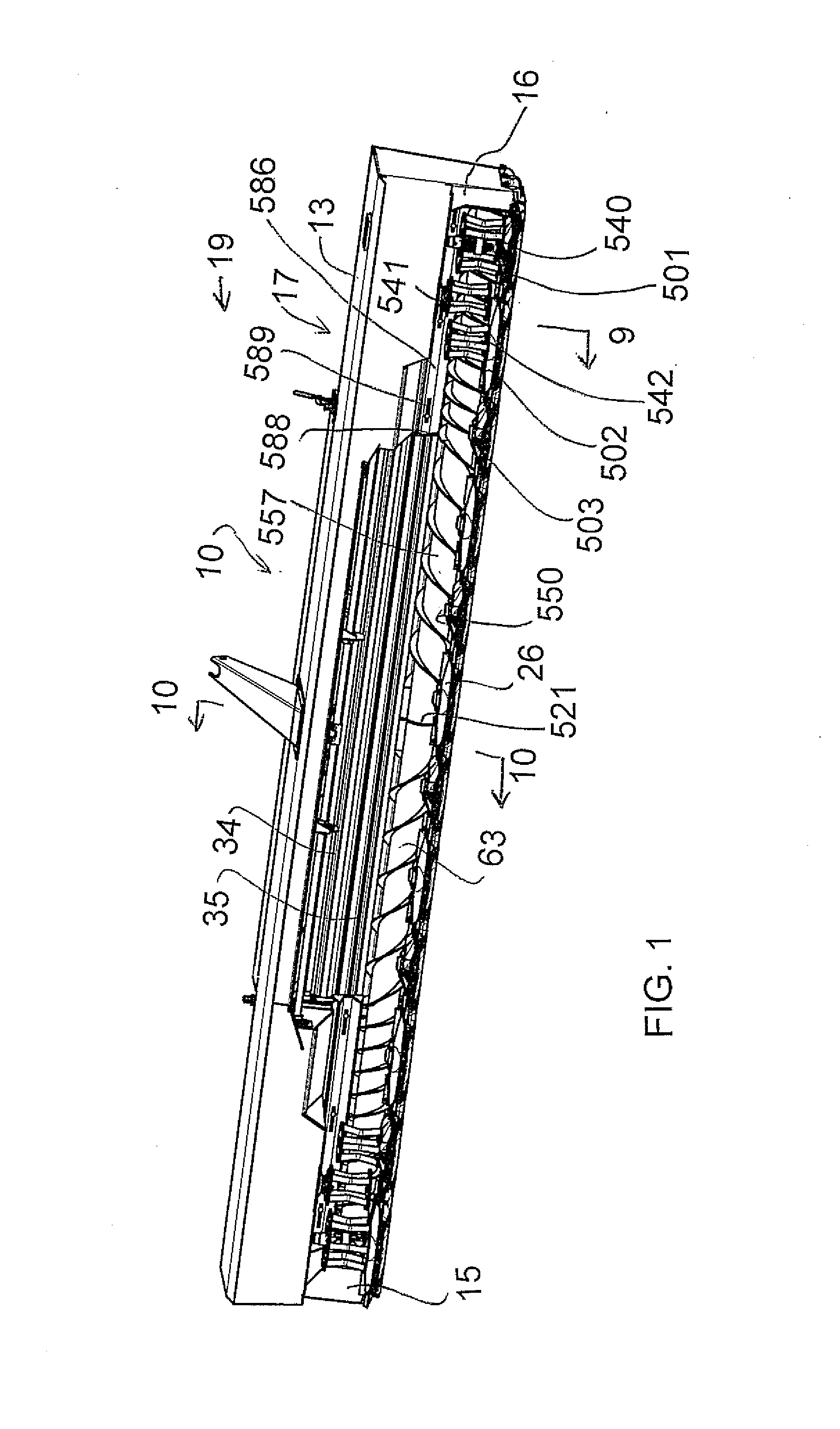
[0099]In FIG. 1 is shown schematically a header for attachment to conventional swather tractor of the well known type having driven ground wheels and rear castor wheels.

[0100]An alternative arrangement can be of the pull-type for towing behind a tractor and the construction of the hitch and support wheels of such a device is well known to a person skilled in this art.

[0101]A front support assembly of the tractor carries the header 14 including left and right lift arms which carry the header in a floating action across the ground along skid plates (not shown) of the header. The header includes side walls 15 and 16 forming part of a frame 17 attached to the conventional transport system of the tractor. The frame carries top covers 18 which support a front skirt 19 in front of the cutter bar.

[0102]The frame 17 includes a main transverse beam 17A which is attached to the tractor. The main beam carries the side walls 15 and 16. The side wails each comprises a vertical wall extending forw...


PUM


Abstract

A crop header has generally horizontal flail disks mounted for driven rotation about generally upright axes. A pair of conditioner rolls is mounted in a discharge opening. A crop converging system includes two over-shot auger elements defined by a common auger shaft with an auger flight carried thereon arranged generally longitudinal of the cutter bar so as to carry the cut crop longitudinally of the cutter bar to the entrance opening. Each auger element is arranged with a forwardmost tangent to the auger flight located behind the axes of the rotary disks and with an outer end thereof spaced outwardly of the respective end of the entrance mouth. The common auger shaft is driven by a common rotary drive with the bottom roll of the conditioner rolls. The augers terminate inwardly of the outer end of the cutter bar to locate the drive inboard of the end plates.

Description

[0001]This application is a continuation-in-part of application Ser. No. 12 / 177,929 filed Jul. 23, 2008 which is now pending.[0002]This application claims the benefit under 35 U.S.C. 119 of Provisional Application 60 / 971,961 filed Sep. 13, 2007.[0003]This application claims the benefit under 35 U.S.C. 119 of Provisional Application 61 / 223,967 filed Jul. 8, 2009.[0004]This invention relates to a crop harvesting header which has a cutter bar across the width of the header which carries and drives a plurality of transversely spaced rotary disks and particularly to an improved arrangement for transferring the cut crop inwardly from outer disks to a discharge opening.BACKGROUND OF THE INVENTION[0005]Crop harvesting headers which use rotary cutters in replacement for the more conventional sickle knife systems have been available for many years. It is well known that such rotary cutters include a cutter bar or gear train which provides the main structural and drive communication components...

Claims


Application Information

Patent Timeline
Patent Type & Authority Applications(United States)
IPC IPC(8): A01D43/00
CPCA01D43/10A01D34/668
Inventor BARNETT, NEIL GORDONSNIDER, GEOFFREY U.
Owner MACDON INDS
Why Eureka
Try Eureka