Ceiling Lift and Ceiling Lift Components

a technology for ceiling lifts and components, applied in the direction of timers, time interval measurement without driving mechanisms, time interval measurement with driving mechanisms, etc., can solve the problems of patients who are difficult to move, attendants may not have enough strength to help patients, and patients who are too heavy to li

Inactive Publication Date: 2010-10-28
PRISM MEDICAL
View PDF10 Cites 33 Cited by
  • Summary
  • Abstract
  • Description
  • Claims
  • Application Information

AI Technical Summary

Benefits of technology

[0012]In one embodiment, a control board of a ceiling lift includes an optocoupler. For example, an optocoupler may be in communication with a controller and a user control of the lift for protecting the controller from electromagnetic noise.

Problems solved by technology

However, often such patients may be too heavy to lift or the attendant may not have enough strength to help the patient move.
Getting up, going to the bathroom and taking a bath, for example, can be difficult for such patients.

Method used


Image

  • Ceiling Lift and Ceiling Lift Components
  • Ceiling Lift and Ceiling Lift Components
  • Ceiling Lift and Ceiling Lift Components

Examples


Embodiment Construction

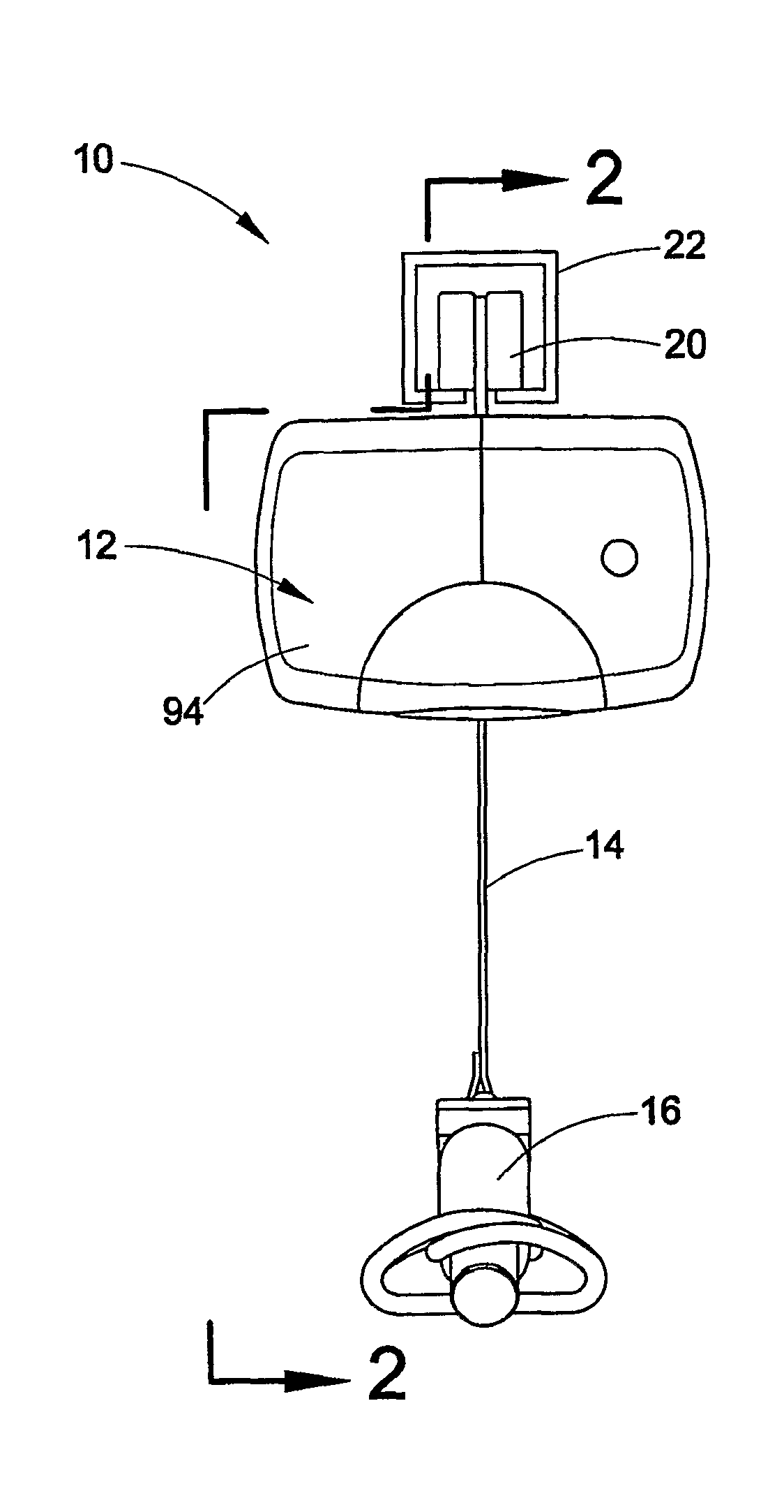
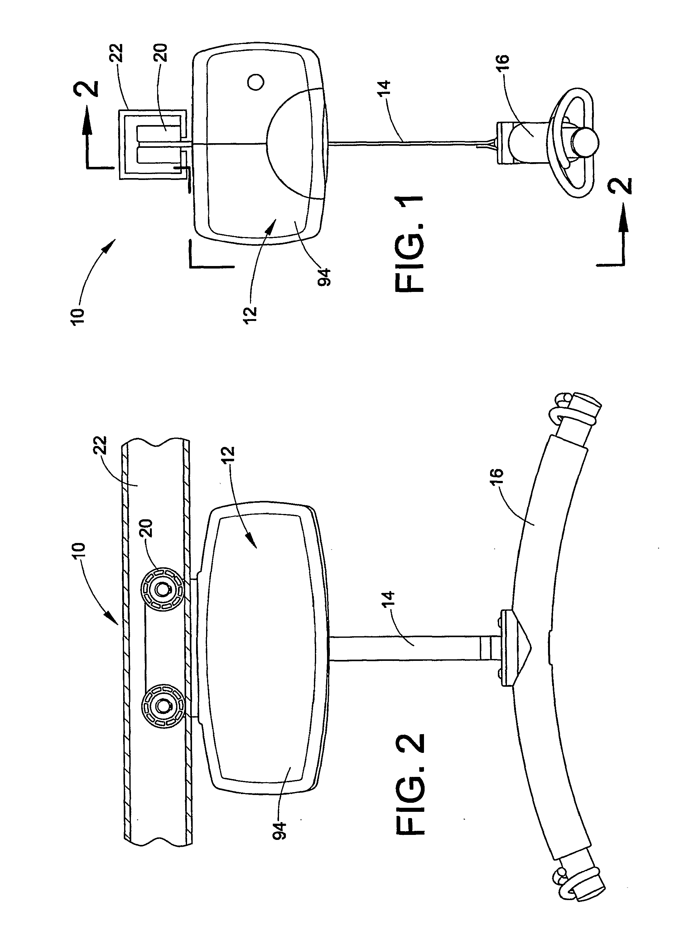
[0039]The present application relates to ceiling lifts 10 and components of ceiling lifts. FIGS. 1 and 2 illustrate one exemplary ceiling lift 10. The ceiling lift 10 includes a lift unit 12, a lift line 14, and a carry bar 16. The lift unit 12 is operated to selectively extend and retract the lift line 14. The carry bar may be attached to a patient sling 18 (see FIG. 10). The line 14 selectively lifts and lowers a patient in the sling 18. The lift unit 12 includes rollers 20 that ride in an elevated track 22. When the patient is lifted, the patient can be moved by rolling the lift unit 12 along the track.

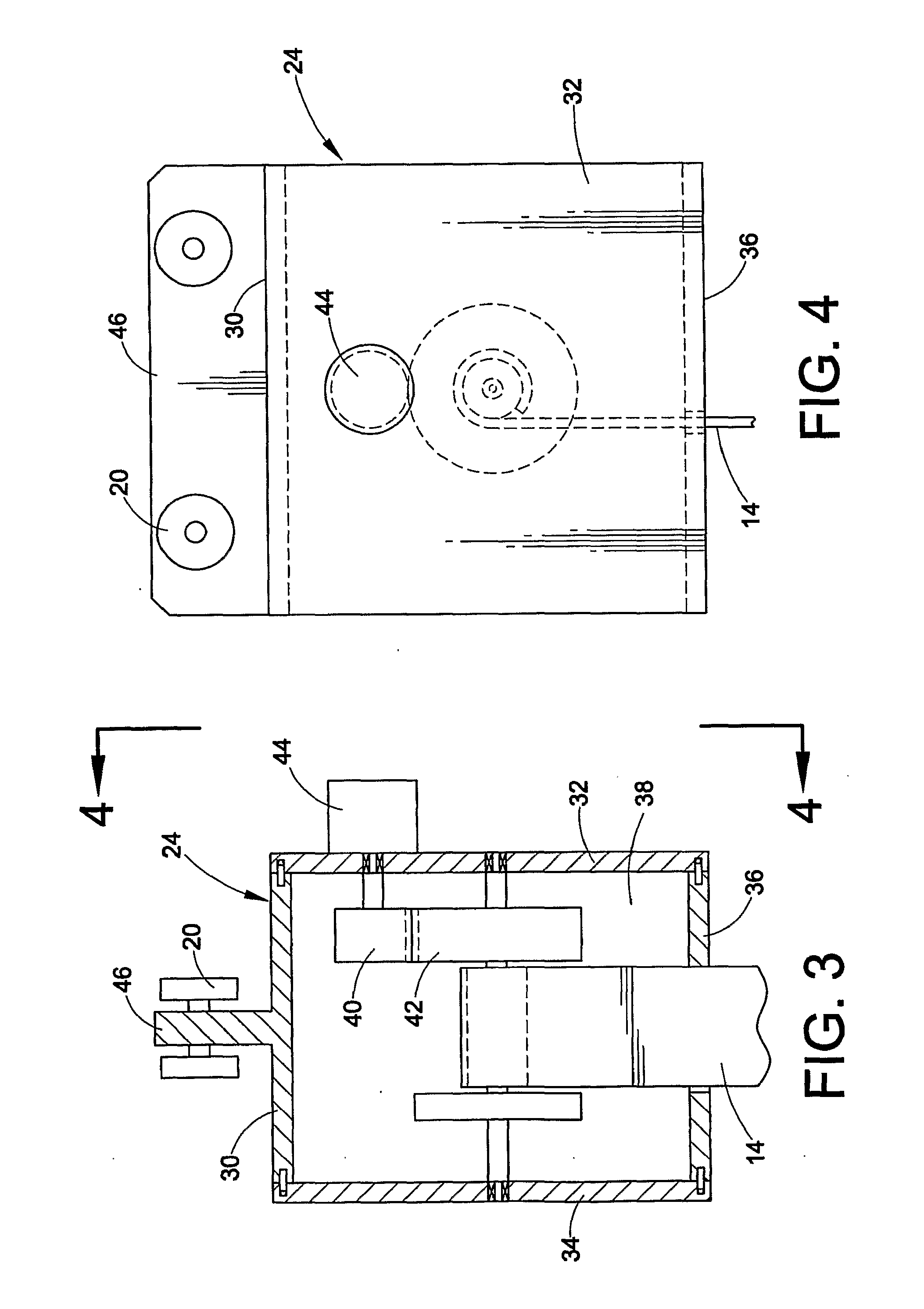
[0040]Referring to FIGS. 3 and 4, the lift unit 12 includes a gear box 24 or drive train support box. In one exemplary embodiment, the gear box 24 is made from separate plates. For example, such a ceiling lift gear box may include a top plate 30, first and second side plates 32, 34, and a bottom plate 36. The side plates 32, 34 are assembled with the top and bottom plates 30, 36 to...


PUM

PropertyMeasurementUnit
volumeaaaaaaaaaa
volumeaaaaaaaaaa
volumeaaaaaaaaaa

Abstract

The present application relates to ceiling lifts and ceiling lift components. One embodiment relates to a ceiling lift gear box that is made from multiple plates. One embodiment relates to a swivel assembly. One embodiment relates to a ceiling lift display. One embodiment relates to use of an optocoupler in a ceiling lift.

Description

[0001]This application claims the benefit of U.S. Provisional Patent Application Ser. No. 60 / 787,389, filed Mar. 30, 2006, the entire disclosure of which is hereby incorporated by reference.BACKGROUND OF THE INVENTION[0002]Personal lift or patient lift devices have been known and used in the past for the purpose of assisting with the mobility of otherwise immobilized patients. An attendant may help physically disabled patients who may have suffered a traumatic injury, stroke or one form of illness or another, and who are unable to move about. However, often such patients may be too heavy to lift or the attendant may not have enough strength to help the patient move. This can be especially true for disabled patients who have reduced mobility but have otherwise normal bodily functions. Getting up, going to the bathroom and taking a bath, for example, can be difficult for such patients.[0003]Personal lift devices that have been used in the past typically include a strap or chain hangin...

Claims


Application Information

Patent Timeline
Patent Type & Authority Applications(United States)
IPC IPC(8): B66C17/00B66D1/02B23P11/00F16G11/00G04F10/00
CPCA61G7/1015A61G7/1042A61G7/1051A61G7/1061Y10T403/32A61G2200/34B66D3/20B66D3/26Y10T29/49826A61G7/1076
Inventor CHEPURNY, MARK P.SHANI, MIKEL
Owner PRISM MEDICAL
Why Eureka
Try Eureka