Wing efficiency for tilt-rotor aircraft

a technology of tilt-rotor aircraft and wing efficiency, which is applied in the direction of rotocraft, vertical landing/take-off aircraft, vehicles, etc., can solve the problems of substantial challenge of dynamic aero-structure instability called whirl flutter and aero-structural dynamic instability, and achieves high wing stiffness, whirl flutter is substantially delayed, and the effect of high flying speed

Inactive Publication Date: 2010-10-28
KAREM ABE
View PDF17 Cites 36 Cited by
  • Summary
  • Abstract
  • Description
  • Claims
  • Application Information

AI Technical Summary

Benefits of technology

[0012]The most successful tilt-rotor rotorcrafts of the last 30 years (Bell XV-15, Bell/Boeing V-22 and Bell/Agusta BA609) use gimbaled rotors, which result in a substantial challenge of dynamic aero-structure instability called whirl flutter. Whirl flutter is an aero structural dynamic instability of the combination of the rotor and the wing. To avoid whirl flutter throughout the flight operation range, the prior art tilt-rotor rotorcrafts require high wing stiffness. By using rigid or semi-rigid rotors, especially ones with low inertia (lightweight blades), whirl flutter is substantially delayed to higher flying speeds and, as a result, longer and less rigid wing can be used with the inventive subject matter without excessive increase in wing weight.
[0013]The increase in wing span and aspect ratio is possible because of the use of rig

Problems solved by technology

The most successful tilt-rotor rotorcrafts of the last 30 years (Bell XV-15, Bell/Boeing V-22 and Bell/Agusta BA609) use gimbaled rotors, which result in a substantial c

Method used


Image

  • Wing efficiency for tilt-rotor aircraft
  • Wing efficiency for tilt-rotor aircraft
  • Wing efficiency for tilt-rotor aircraft

Examples


Embodiment Construction

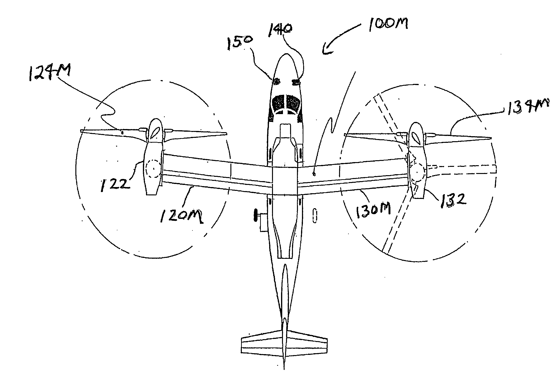
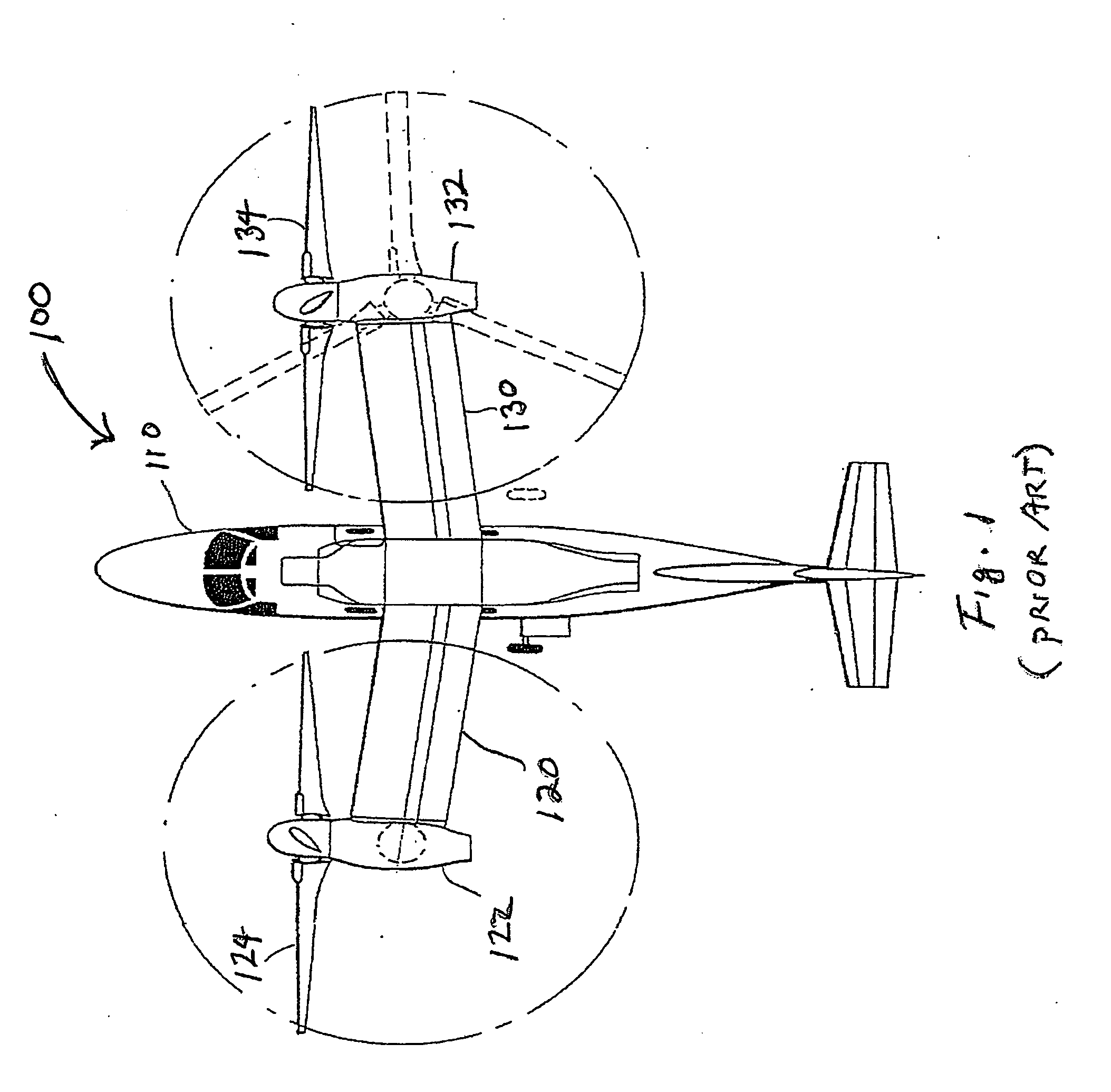
[0018]In FIG. 1 a rotorcraft 100 generally includes a fuselage 110, a left wing 120 with tilting nacelle 122 and rotor 124, and a right wing 130 with tilting nacelle 132 and rotor 134. As with other prior art aircraft of this type, the complete wing (120 plus 130 plus the center section attached to the fuselage) has a wing aspect ratio is 5.5. To illustrate the tilt-rotor aspect of the design in a simplified manner, the nacelles 122, 132, and the right rotor 134 are shown in the lifting configuration in dashed lines.

[0019]It should be appreciated that although rotorcraft 100 is depicted here in a substantially to-scale model of a Bell / Agusta BA 609, the drawing should be interpreted as being representative of tilt-rotorcraft in general. In particular, it is contemplated that the inventive subject matter could also be applied to quad tilt-rotor configuration, etc.

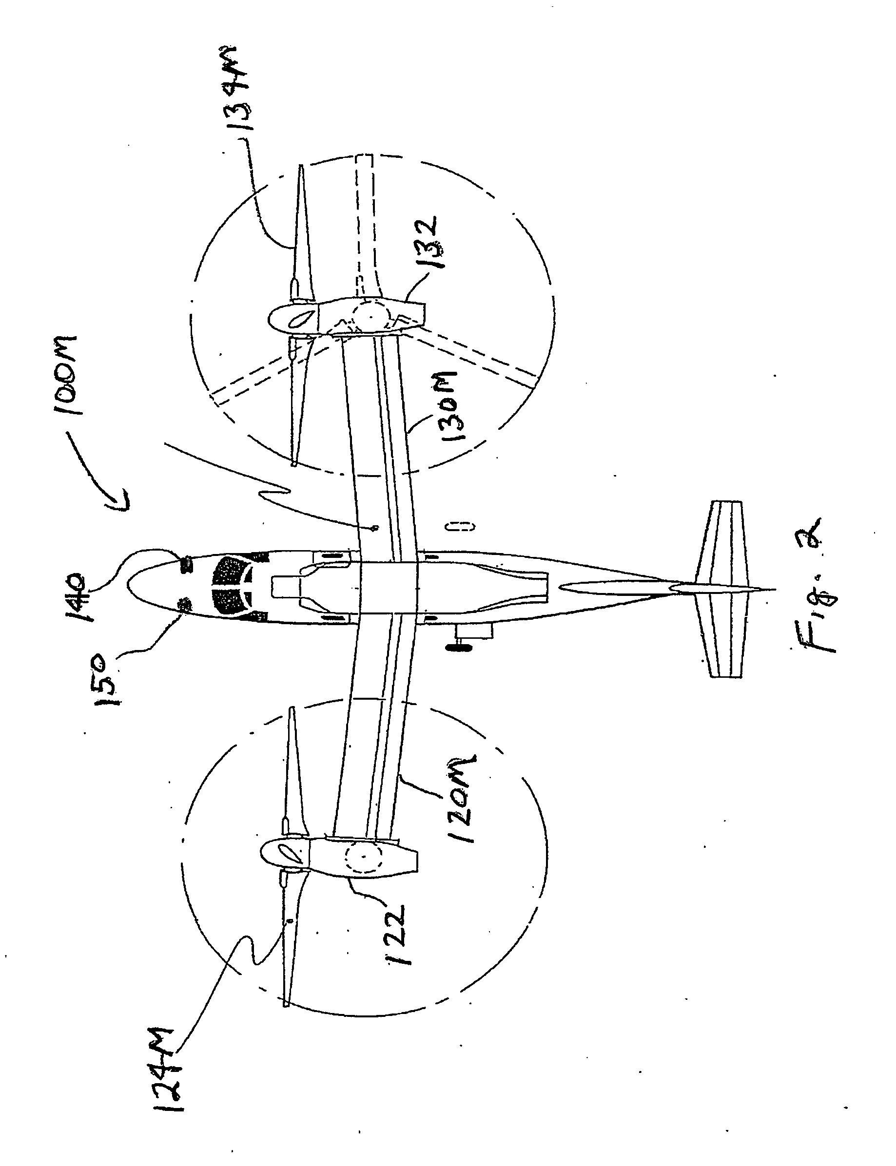
[0020]In FIG. 2 the rotorcraft 100M of FIG. 1 has been modified to have a wing aspect ratio of 9.3, which is a 69% increas...


PUM


Abstract

Rotorcraft wings disposed between tilt-rotor nacelles have particularly high aspect ratios for tilt-rotor rotorcraft, including for example at least 6, 7, 8, or higher. The increase in wing span and aspect ratio is possible because of the use of rigid and semi-rigid rotors, and/or higher modulus of elasticity materials allows increases the stiffness of the wings to the level required for avoiding whirl flutter. Tilt-rotor aircraft having high aspect ratio wings can advantageously further include a controller that provides reduced RPM in a forward flight relative to hover, and/or a controller that provides variable speed, (a so-called “Optimum Speed Tilt Rotor”) as set forth in U.S. Pat. No. 6,641,365 to Karem (November 2003).

Description

[0001]This application claims priority to U.S. Provisional Application Ser No. 60 / 708805 filed Aug. 15, 2005.FIELD OF THE INVENTION[0002]The field of the invention is tilt-rotor aircraft.BACKGROUND OF THE INVENTION[0003]The cruise efficiency of aircraft as measured by its payload carried times the distance traveled per consumed fuel (for example Lb of Payload×Mile traveled / Lb of consumed fuel) is proportional to the ratio between lift and drag of the aircraft in cruise flight.[0004]The best (highest) lift / drag ratio of a fixed wing aircraft is strongly related to the ratio of wing span to the size of the aircraft. For example, competition gliders use very small and streamlined fuselage (for low drag) and large span wings for best lift / drag (glide ratio).[0005]The flight speed for best lift / drag ratio, at given aircraft weight and altitude is a function of wing area. An aircraft with smaller wing area will have higher speed for best lift / drag. The ratio of wing span squared to wing a...

Claims


Application Information

Patent Timeline
IPC IPC(8): B64C27/22
CPCB64C29/0033
Inventor KAREM, ABE
Owner KAREM ABE
Why Eureka
Try Eureka