Synthesizer, synthesizer module, and reception device and electronic device using same

a synthesizer and module technology, applied in the direction of generator stabilization, pulse automatic control, oscillating generators, etc., can solve the problems of increasing the bit error rate, affecting the output frequency of the synthesizer, so as to prevent the deterioration of phase noise and suppress the change of output frequency

Active Publication Date: 2010-10-28
CONVERSANT INTPROP MANAGEMENT INC
View PDF4 Cites 5 Cited by
  • Summary
  • Abstract
  • Description
  • Claims
  • Application Information

AI Technical Summary

Benefits of technology

[0014]According to such a configuration, the synthesizer of the present invention changes the frequency division ratio without resetting the frequency divider (in a state in which the past cumulative addition value is kept) when the frequency division ratio of the frequency divider is changed according to th

Problems solved by technology

As a result, a phase noise that is a ratio of electric power of the oscillating frequency to a noise in the vicinity thereof may be large.
Since the oscillating frequency is generally used for a local signal and the like, deterioration of phase noise performance of the local signal may cause considerable deterioration of a C/N (Carrier/Noise) prop

Method used


Image

  • Synthesizer, synthesizer module, and reception device and electronic device using same
  • Synthesizer, synthesizer module, and reception device and electronic device using same
  • Synthesizer, synthesizer module, and reception device and electronic device using same

Examples


Embodiment Construction

Exemplary Embodiment

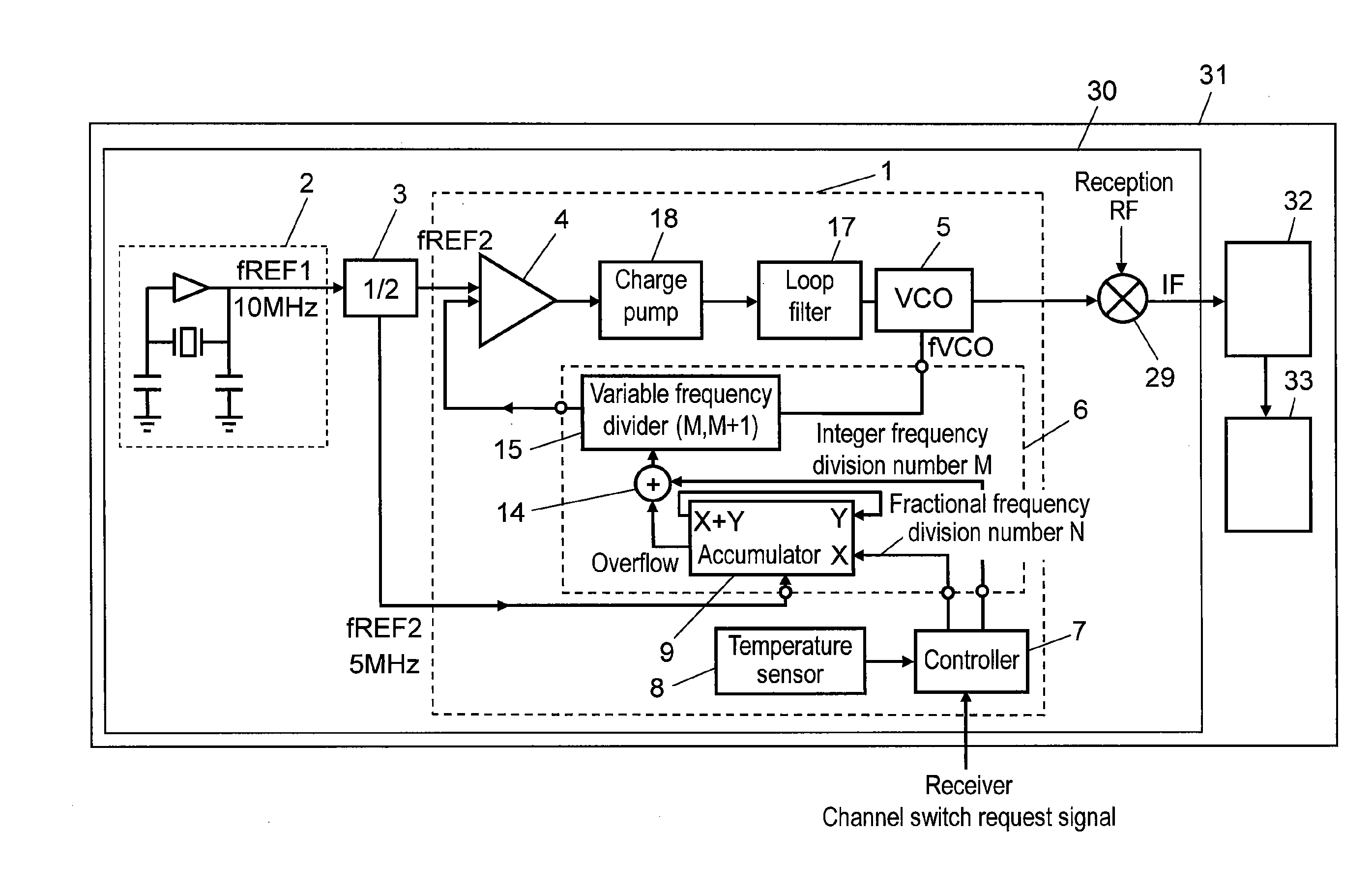
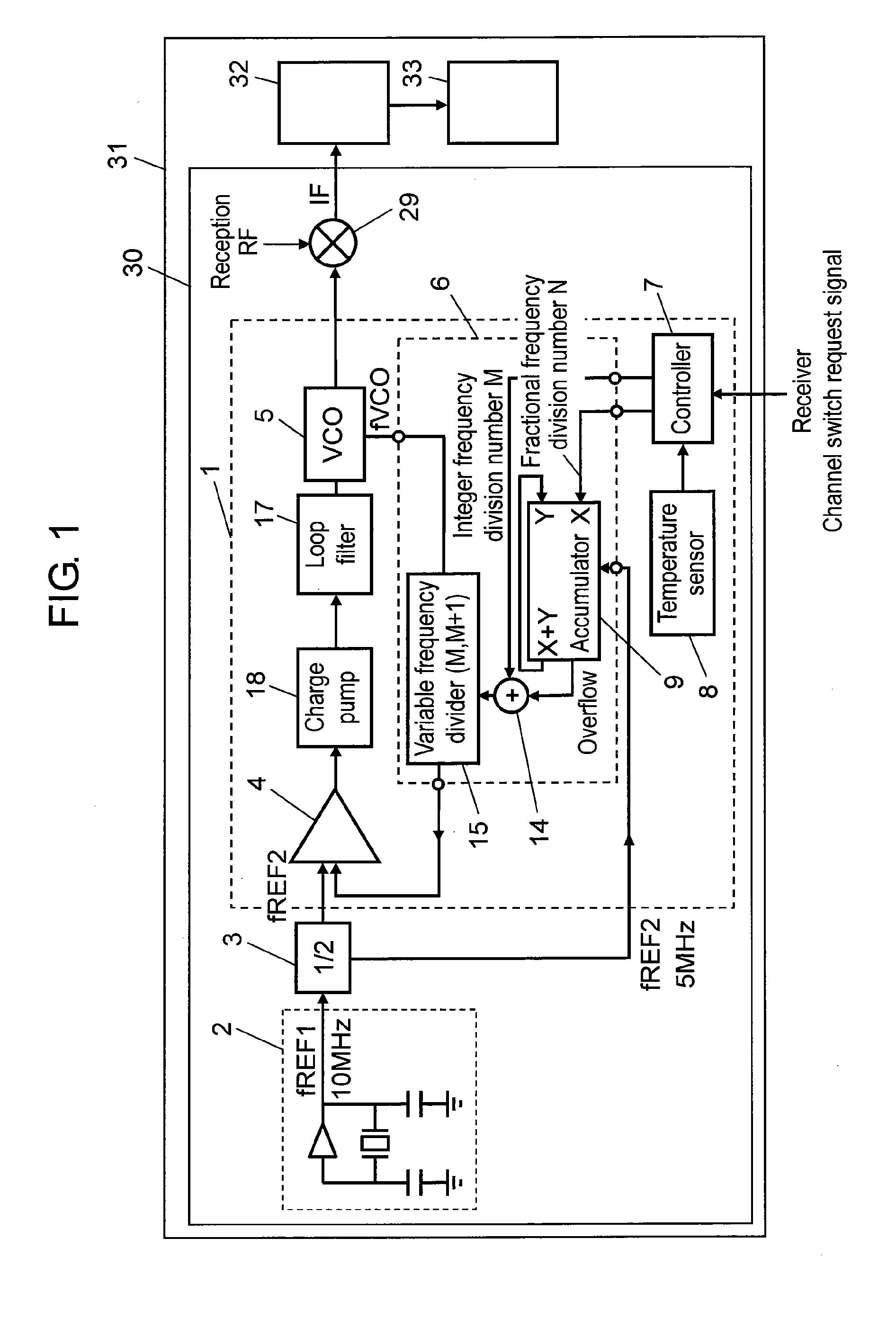
[0072]Hereinafter, a synthesizer in accordance with a first exemplary embodiment is described with reference to drawings. FIG. 1 is a configuration diagram showing an electronic device using a synthesizer in accordance with one exemplary embodiment of the present invention.

[0073]In FIG. 1, reception device 30 includes synthesizer 1 and oscillator (hereinafter, referred to as “MEMS oscillator”) 2 as MEMS (Micro Electro Mechanical Systems) element for outputting a reference oscillation signal. Reference oscillating frequency fREF1 of MEMS oscillator 2 is 10 MHz. Reception device 30 further includes first frequency divider 3 for 1 / 2 dividing an output from MEMS oscillator 2, and mixer 29 for converting a frequency of a reception RF (Radio Frequency) signal based on an oscillation signal output from synthesizer 1. Electronic device 31 includes signal processing section 32 connected to the output side of mixer 29 of reception device 30, and display section 33 connecte...


PUM


Abstract

A synthesizer including an oscillator for outputting an oscillation signal based on an output signal from a comparator, a frequency divider for dividing a frequency of an output signal from the oscillator based on control from a controller, and a temperature sensor for detecting an error between a preset frequency and a frequency based on a reference oscillation signal. The comparator compares an output signal from the frequency divider with an output signal from a MEMS oscillator and outputs a signal indicating the comparison result to the oscillator. The controller changes the frequency division ratio of the frequency divider based on an output signal from the temperature sensor and changes the frequency division ratio in a state in which the frequency division ratio is kept at the past value. Thus, phase noise deterioration in the synthesizer can be suppressed.

Description

[0001]This application is a U.S. National Phase Application of PCT International Application PCT / JP2008 / 003256.TECHNICAL FIELD[0002]The present invention relates to a synthesizer, a synthesizer module, and a receiver and an electronic device using the same.BACKGROUND ART[0003]A conventional synthesizer carrying out temperature compensation of a reference oscillator is described hereinafter with reference to FIG. 14, which is disclosed in, for example, Patent Document 1.[0004]FIG. 14 is a block diagram showing a conventional synthesizer carrying out temperature compensation of a reference oscillator. In conventional synthesizer 100 shown in FIG. 14, a reference oscillation signal output from reference frequency oscillator 101 is divided by first frequency divider 102, and then input into comparator 103. Furthermore, an output signal from comparator 103 is integrated in low-pass filter 104, and converted into a signal having a frequency near a direct current. Based on a voltage value ...

Claims


Application Information

Patent Timeline
IPC IPC(8): H03L7/08
CPCH03L7/1976H03L1/027
Inventor NAMBA, AKIHIKOFUJII, TAKESHITSUKIO, YASUNOBU
Owner CONVERSANT INTPROP MANAGEMENT INC
Why Eureka
Try Eureka