
Method of identifying positions of wheel modules

a technology of positioning position and wheel module, which is applied in the direction of transportation and packaging, instruments, and static/dynamic balance measurement, etc., can solve the problems of affecting the fuel economy of associated vehicles, affecting and a relatively modest degree of energy dissipation. , to achieve the effect of enhancing the safety and reliability of such vehicles

Active Publication Date: 2010-10-28
VOLVO LASTVAGNAR AB
View PDF0 Cites 60 Cited by
  • Summary
  • Abstract
  • Description
  • Claims
  • Application Information

AI Technical Summary

Benefits of technology

[0010]An object of the present invention is to provide an improved method of identifying locations of wheel and / or tyre monitors included in apparatus of vehicles which is capable of enhancing safety and reliability of such vehicles.
[0015]The invention is of advantage in that it provides a simple practical method of identifying the locations whereat the one or more modules of the apparatus are located on wheels of the vehicle.
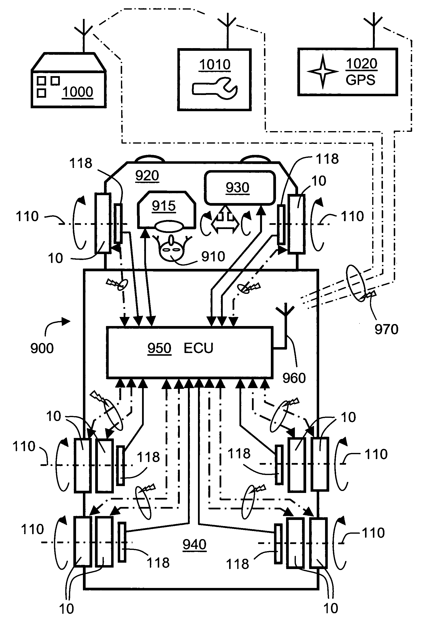
[0021]Optionally, when implementing the method, the vehicle is driven at the partially transverse angle so as to result in signals from the one or more modules being temporally mutually different between corresponding left-hand-side and right-hand-side wheels of the vehicle, thereby enabling the processing arrangement to distinguish locations whereat the one or modules along the vehicle and distinguish whether the one or more modules are on a left-hand side or a right-hand side of the vehicle, in the event the overall direction of the elongate is known, such that information is available of which side of the elongated feature is expected to generate a signal first. From such information, that is if the elongated feature is inclined from the left to the right side, having the left side closer to the vehicle, or vice versa, information of an expected temporal separation between an impact of the wheels on the left and right sides respectively can be established. The respective sensor modules arranged on the left and right sides can therefore be identified by the temporal separation of the received input signals from the modules. The overall direction of the elongated feature can be known, either by using a test rig where the direction of the elongated feature is known, or by use of a road monitoring system which by image recognition can identify an elongated object and determine a general direction of the elongate feature with respect to the vehicle. Preferably the inclination of the elongate feature is selected so that the temporal separation between wheels arranged on the left and right side is smaller than the temporal separation between wheels arranged on different axes of the vehicle. By studying the geometry of the vehicle and identifying the distance between a left and right tyre arranged on the same axle and comparing it with a distance between two axles of the vehicle which are closest to each other a suitable limit for the inclination of the elongated feature can be selected. Normally the limit can be selected to be less than 45° for a vehicle having two axles or less than 30° for vehicles having three or more axles. Around 15-20° would provide for a suitable separation between left and right and separation between each axle for a vehicle having three axles. Selection of an appropriate inclination for an elongated feature arranged in a test rig is straight forward. The road monitoring system can be arranged to determine the inclination of an identified elongated feature with respect to a heading direction of the vehicle. The system may then be allowed to perform the method according to this invention only when the inclination of the detected elongated feature is within a selected appropriate range.
[0039]Optionally, when implementing the system, the control centre is operable to organise the maintenance or repair at the identified one or more service facilities automatically without one or more drivers of the one or more vehicles needing to intervene.
[0040]Optionally, in the system, the one or more vehicles include global position sensing apparatus thereon coupled in communication with the wheel-monitoring apparatus for enabling the one or more vehicles to communicate their position to the control centre, so that the control centre is operable to identify one or more service facilities most suitably geographically disposed to service the one or more vehicles.

Problems solved by technology

Moreover, during their operating lifetime, tyres are required to survive potentially up to several thousand or even millions of deformation cycles without exhibiting work-hardening failure, and yet exhibit a relatively modest degree of energy dissipation therein as a result of viscous dampening effects.
Tyre failure during operation can potentially result in immobilization of an associated vehicle or even accident.
Moreover, tyres operated at unsuitable pressures can adversely influence associated vehicle fuel economy; fuel economy is becoming increasingly pertinent in view of increases in fuel costs as well as in view of carbon dioxide generation and its perceived impact on World climate change.
On account of tyre condition being an important factor influencing vehicle operating economy and safety, a technical problem is therefore how to provide more advanced wheel and tyre monitoring.
However, it is still feasible that tyres and wheels undergo events which escape the attention of such rigorous maintenance routines and can therefore represent a potential hazard.
For example, wheels are potentially exchanged between vehicles either without authorization of respective vehicles owners which can thereby circumvent such rigorous maintenance routines or by way of theft.
Moreover, wheel hubs are susceptible over their operating lifetime to being provided with numerous replacement tyres.
However, there then arises a technical problem regarding how to manage complex configurations of tyre and wheel monitors, especially when tyres are replaced at mutually different times and wheels and their tyres are susceptible to being retained in storage over periods when exchanging between summer and winder tyres.

Method used


Image

  • Method of identifying positions of wheel modules
  • Method of identifying positions of wheel modules
  • Method of identifying positions of wheel modules

Examples


Embodiment Construction

1. Context of the Present Invention

[0071]Commercial enterprises which operate fleets of vehicles, for example fleets of heavy commercial vehicles, face different problems with vehicle maintenance and safety in comparison to private automobile owners for which simple contemporary tyre monitoring devices have already been developed as elucidated in the foregoing. Reliability and safety for an enterprise operating a fleet of vehicles is extremely important on account of one accident, breakdown or legal incident potentially adversely affecting the enterprise's reputation and relationship with its customers. Vehicle maintenance, and avoidance of vehicle technical problems before they arise and cause disruption, is of considerable importance to enterprises operating fleets of vehicles.

[0072]In a fleet of vehicles, for example heavy commercial vehicles, there are multiple vehicles, and a set of wheel hubs for the vehicles which are equipped with new tyres at various times. Wheel hubs can p...


PUM


Abstract

There is provided a method of identifying locations of modules (400) of an apparatus (600, 680, 690, 2200) for monitoring wheels (10) of a vehicle (900). The sensor modules (400) operatively revolving with the wheels (10). The modules (400) communicate with a processing arrangement (710, ECU 950) of the vehicle (900). The modules (400) sense a physical parameter of the wheels (10) and generate corresponding sensor signals for the processing arrangement (950). The processing arrangement (710, ECU 950) processes the sensor signals to compute information indicative of operation of the wheels (10). The apparatus (1) also includes a sensor arrangement (118) for sensing an angular orientation (0) of the wheels (10). The method includes steps of: (b) arranging an elongate feature (1100) in an at least partially transverse direction relative to a direction of travel of the vehicle (900); (c) driving the vehicle (900) over the elongate feature (1100) to cause the wheels (10), together with their associated modules (400), to contact momentarily onto the elongate feature (1100) and communicating signals including signal components stimulated by contact of the wheels (10) onto the elongate feature (1100) to the processing arrangement (950), the signals identifying a time at which their wheels (10) contacted onto the elongate feature (1100) and identification codes (ID) of the modules (400); and (d) from a temporal sequence of the signals received at the processing arrangement (950), identifying whereat modules (400) are located on the wheels (10) of the vehicle (900).

Description

FIELD OF THE INVENTION[0001]The present invention relates to methods of identifying positions of wheel modules included in wheels and / or their associated tyres; for example, to a method of identifying positions of wheel modules operable to monitor characteristics of wheels and / or their associated tyres and conveying information indicative of these aforementioned characteristics via a communication link to an electronic control unit (ECU) and / or control system, for example for user-display. Moreover, the present invention also concerns wheel modules for use in implementing aforementioned methods. Additionally, the invention relates to methods of servicing vehicles including such wheel modules. Furthermore, the present invention also relates to software and software products executable on computing hardware for executing these aforesaid methods.BACKGROUND OF THE INVENTION[0002]Tyres, also known as “tires” in American-English, are critical components in road vehicles. Contemporary tyre...

Claims


Application Information

Patent Timeline
Patent Type & Authority Applications(United States)
IPC IPC(8): G06F7/00G06Q10/00G01S19/51G06Q50/00G06Q10/06
CPCB60C23/0416G06Q10/063G01M17/013G01M1/28B60C23/0477
Inventor CARRESJO, ERIKHASSELBERG, PER
Owner VOLVO LASTVAGNAR AB
Learn More