
Display apparatus, data transmitting method in display apparatus, transmission apparatus, and data receiving method in transmission apparatus

a display apparatus and data transmitting technology, applied in the field of display apparatus, can solve the problems of difficult installation of a tuner (broadcast reception section) on personal computers, and achieve the effect of effectively using the broadcast reception section

Inactive Publication Date: 2010-10-28
SONY CORP
View PDF14 Cites 12 Cited by
  • Summary
  • Abstract
  • Description
  • Claims
  • Application Information

AI Technical Summary

Benefits of technology

[0033]According to the present invention, in a display apparatus for displaying a video signal received from an external device via a transmission path or an image based on stream data obtained in a broadcast reception section, the stream data obtained in the broadcast reception section is transmitted to the external device by a communication section for bidirectional communication by use of a predetermined line configuring the transmission path, thereby enabling the external device to effectively use the broadcast reception section.
[0003]Also, the present invention relates to a transmission apparatus and so on, the transmission apparatus transmitting a video signal to an external device via a transmission path, in which stream data obtained in a broadcast reception section of that external device is received from the external device by a communication section for bidirectional communication by use of a predetermined line configuring the transmission path, thereby effectively using the broadcast reception section of the external device.

Problems solved by technology

However, with the downsizing and low pricing of personal computers, the installation of a tuner (broadcast reception section) on personal computers has become difficult.

Method used


Image

  • Display apparatus, data transmitting method in display apparatus, transmission apparatus, and data receiving method in transmission apparatus
  • Display apparatus, data transmitting method in display apparatus, transmission apparatus, and data receiving method in transmission apparatus
  • Display apparatus, data transmitting method in display apparatus, transmission apparatus, and data receiving method in transmission apparatus

Examples


Embodiment Construction

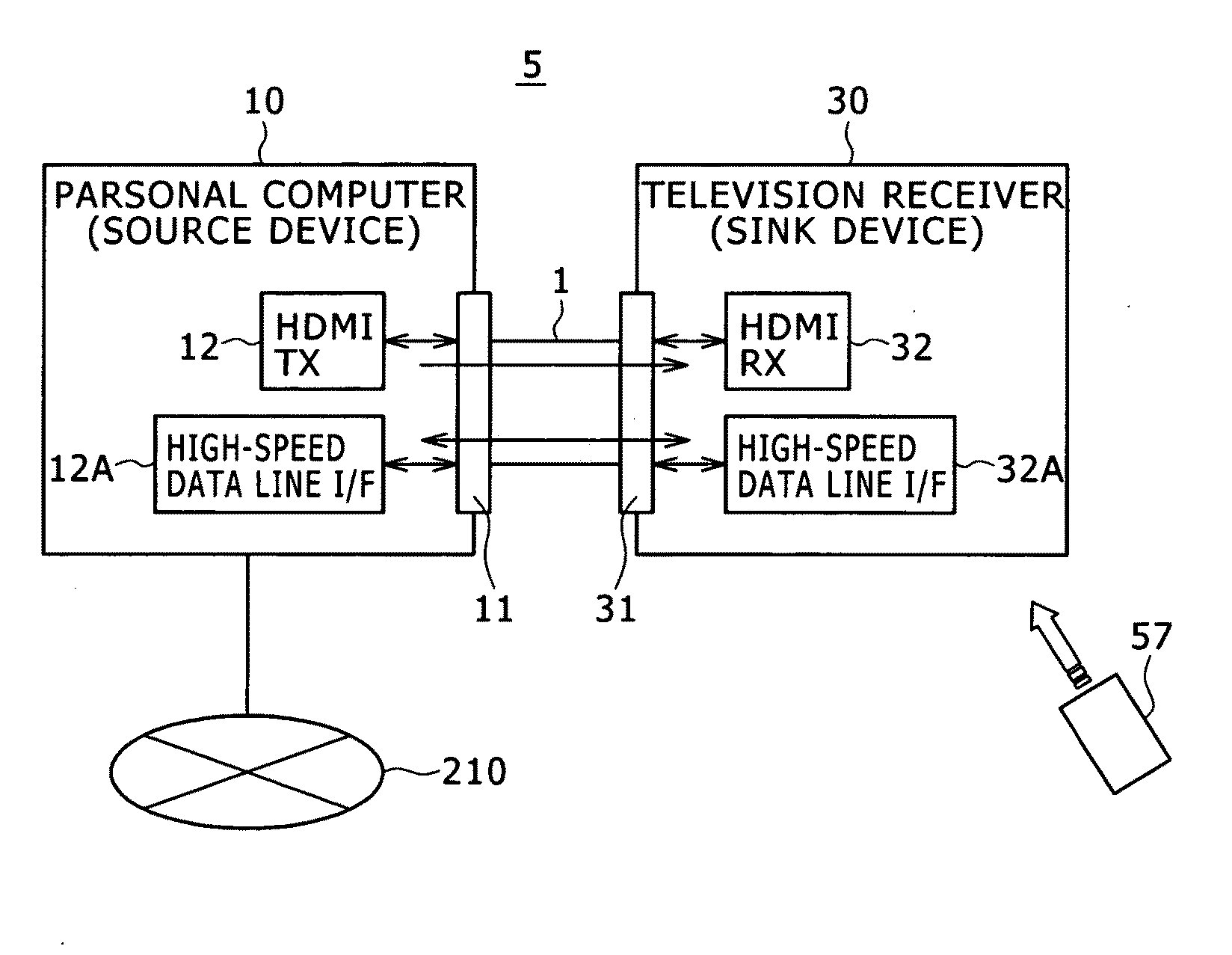
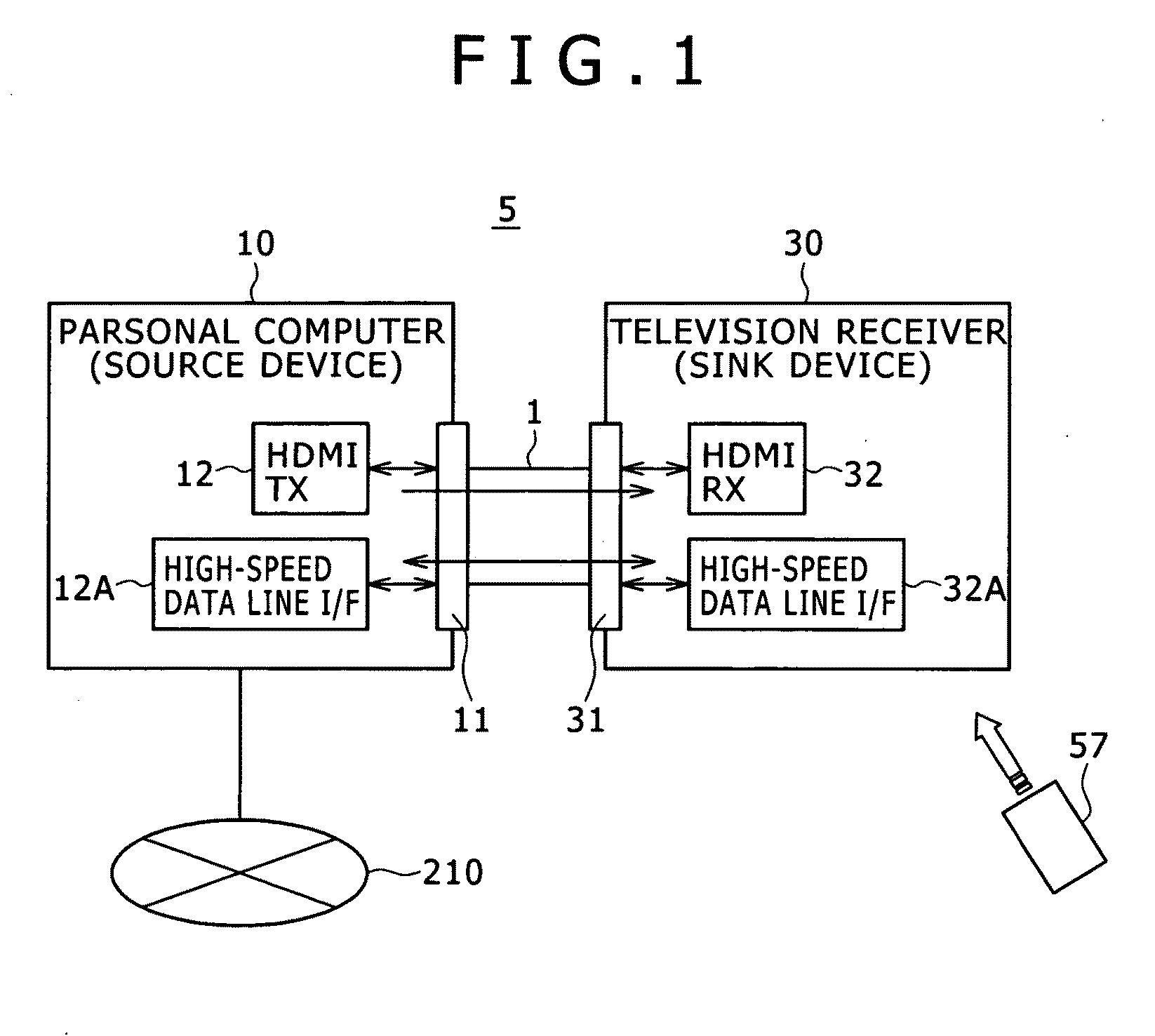
[0063]The present invention will be described in further detail by way of embodiments thereof with reference to the accompanying drawings. Now, referring to FIG. 1, there are shown exemplary configurations of an AV (Audio Visual) system 5 practiced as one embodiment of the invention.

[0064]The AV system 5 has a personal computer (PC) 10 as a source device and a television receiver 30 as a sink device. The personal computer 10 and the television receiver 30 are interconnected with an HDMI cable 1. The personal computer 10 is connected to the Internet 210.

[0065]The personal computer 10 has an HDMI terminal 11 connected with an HDMI transmission section (HDMI TX) 12 and a high-speed data line interface 12A. The television receiver 30 has HDMI terminals 31 connected with HDMI reception sections (HDMI RX) 32 and high-speed data line interface 32A. One end of the HDMI cable 1 is connected to the HDMI terminal 11 of the personal computer 10 and one end of the HDMI cable 1 is connected to th...


PUM


Abstract

To effectively use a broadcast reception section (tuner) of a display apparatus such as a television receiver. A personal computer (PC) 10 and a television receiver (TV) 30 are interconnected with one HDMI cable (1). For the transmission of a video signal from the PC 10 to the TV (30), a TMDS channel of the HDMI cable (1) is used. A high-speed data line for executing bidirectional communication using a predetermined line (for example, a reserve line, an HPD line) of the HDMI cable is arranged. Stream data obtained in a broadcast reception section (tuner) of the TV 30 is transmitted to the PC 10 by use of the high-speed data line. The PC 10 records the received stream data or executes image synthesis processing and the line by use of the stream data. The PC 10 transmits the video signal after synthesis processing to the TV 30 over a TDMS channel. On the TV 30, a desktop screen, a reproduced image, a web page, and the like are simultaneously displayed along with a television screen.

Description

TECHNICAL FIELD[0001]The present invention relates to a display apparatus, a data transmitting method in the display apparatus, a transmission apparatus, and a data receiving method in the transmission apparatus.[0002]In detail, the present invention relates to a display apparatus and so on, the display apparatus displaying a video signal received from an external device via a transmission path or an image based on stream data obtained in a broadcast reception section, in which the stream data obtained in the broadcast reception section is transmitted to the external device by a communication section for bidirectional communication by use of a predetermined line configuring the transmission path, thereby enabling the external device to effectively use the broadcast reception section.[0003]Also, the present invention relates to a transmission apparatus and so on, the transmission apparatus transmitting a video signal to an external device via a transmission path, in which stream data...

Claims


Application Information

Patent Timeline
IPC IPC(8): H04N5/445H04N7/16H04N5/44H04N7/173
CPCH04N5/765H04N5/775H04N5/781H04N5/85H04N21/43632H04N9/8042H04N21/4113H04N21/4122H04N5/907
Inventor KAMON, HIDEKAZUKITARU, KATSUNORINAKAJIMA, YASUHISA
Owner SONY CORP
Learn More