
Direct transfer axial tangential onboard injector system (TOBI) with self-supporting seal plate

a technology of injector system and seal plate, which is applied in the direction of mechanical equipment, machines/engines, liquid fuel engines, etc., can solve the problems of reducing swirl ratio, requiring cooling, and increasing pressure and temperature, so as to reduce the swirl ratio and reduce the temperature of the air

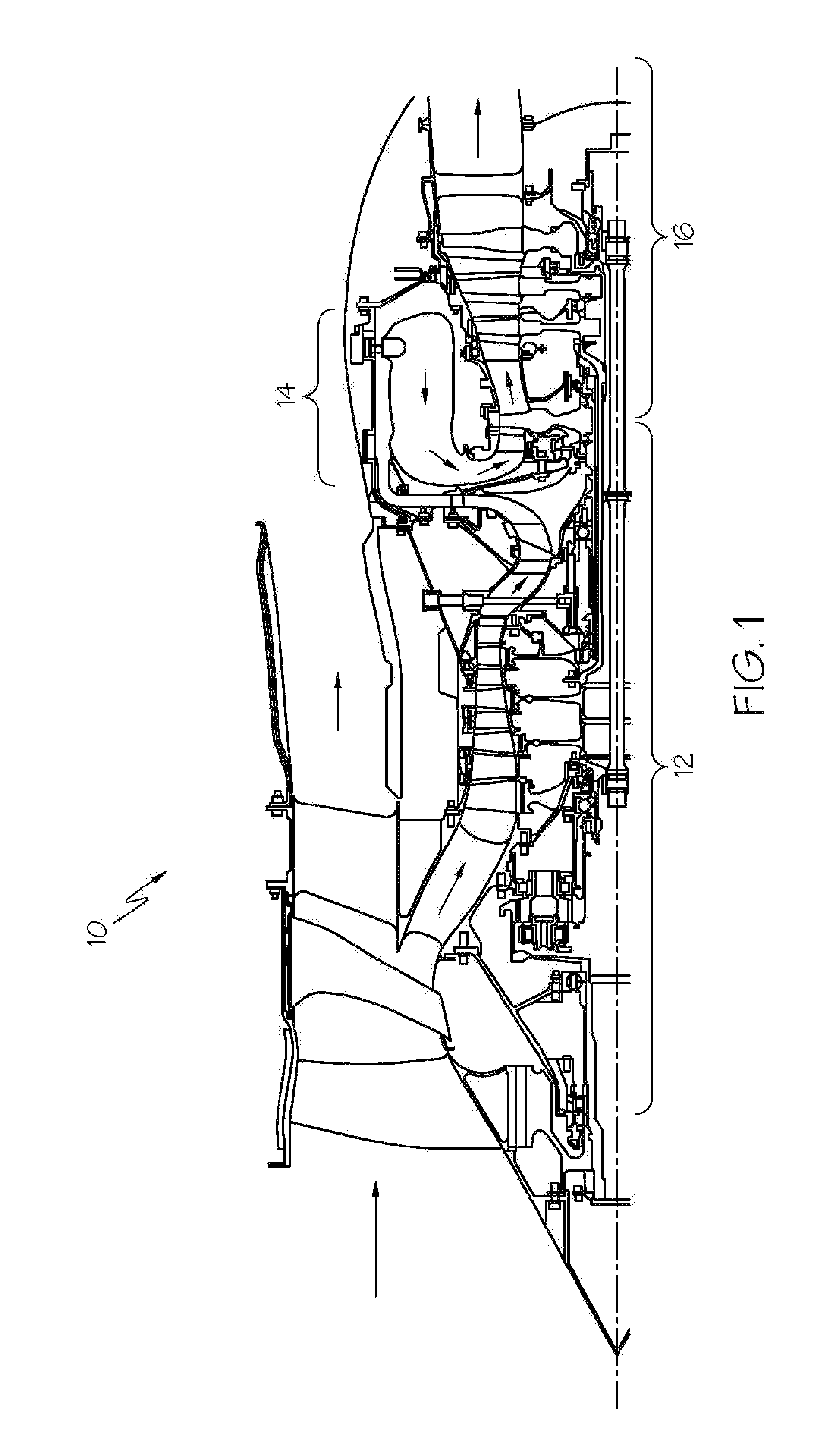
Active Publication Date: 2010-11-04
HONEYWELL INT INC
View PDF14 Cites 35 Cited by
  • Summary
  • Abstract
  • Description
  • Claims
  • Application Information

AI Technical Summary

Problems solved by technology

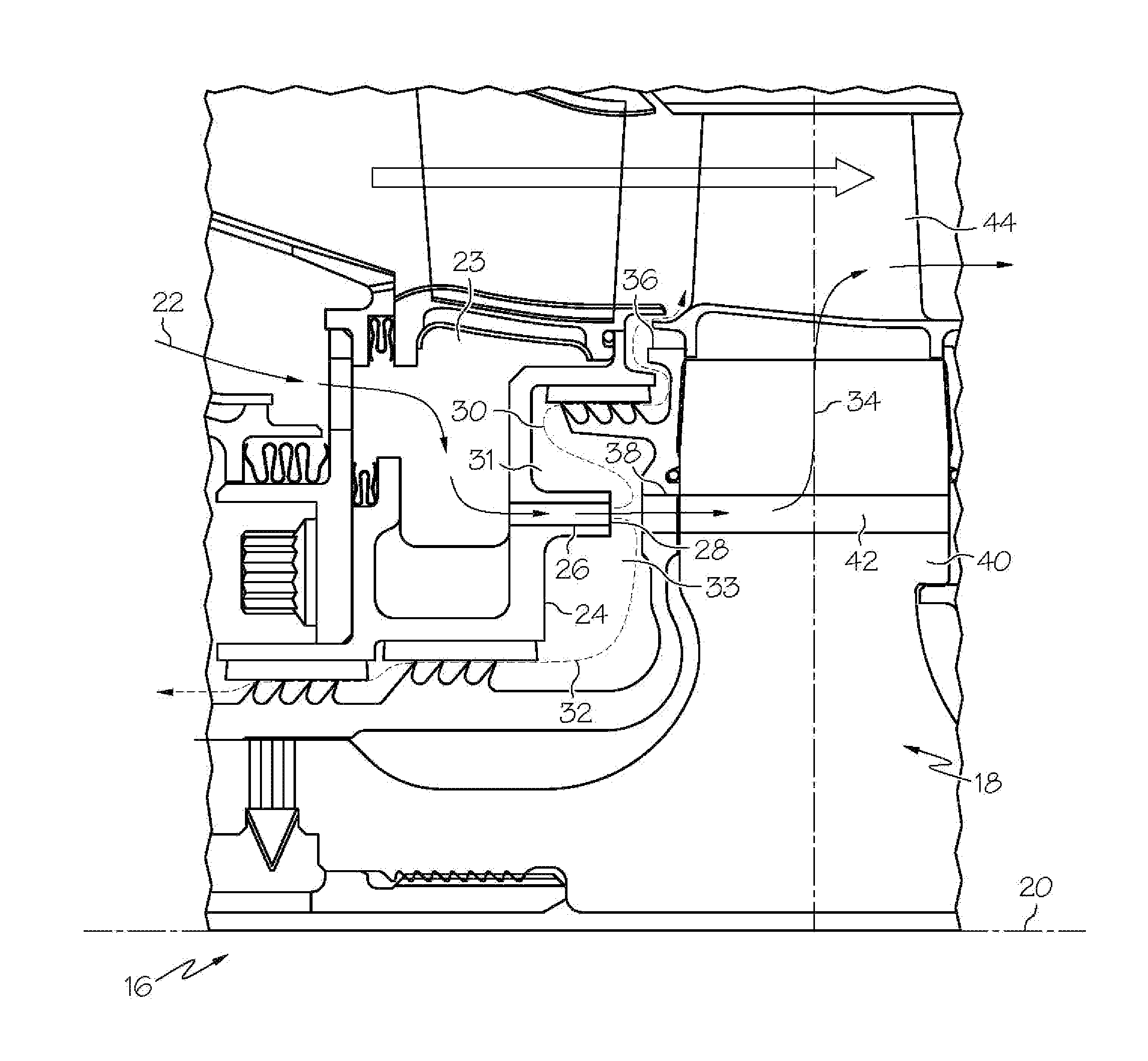
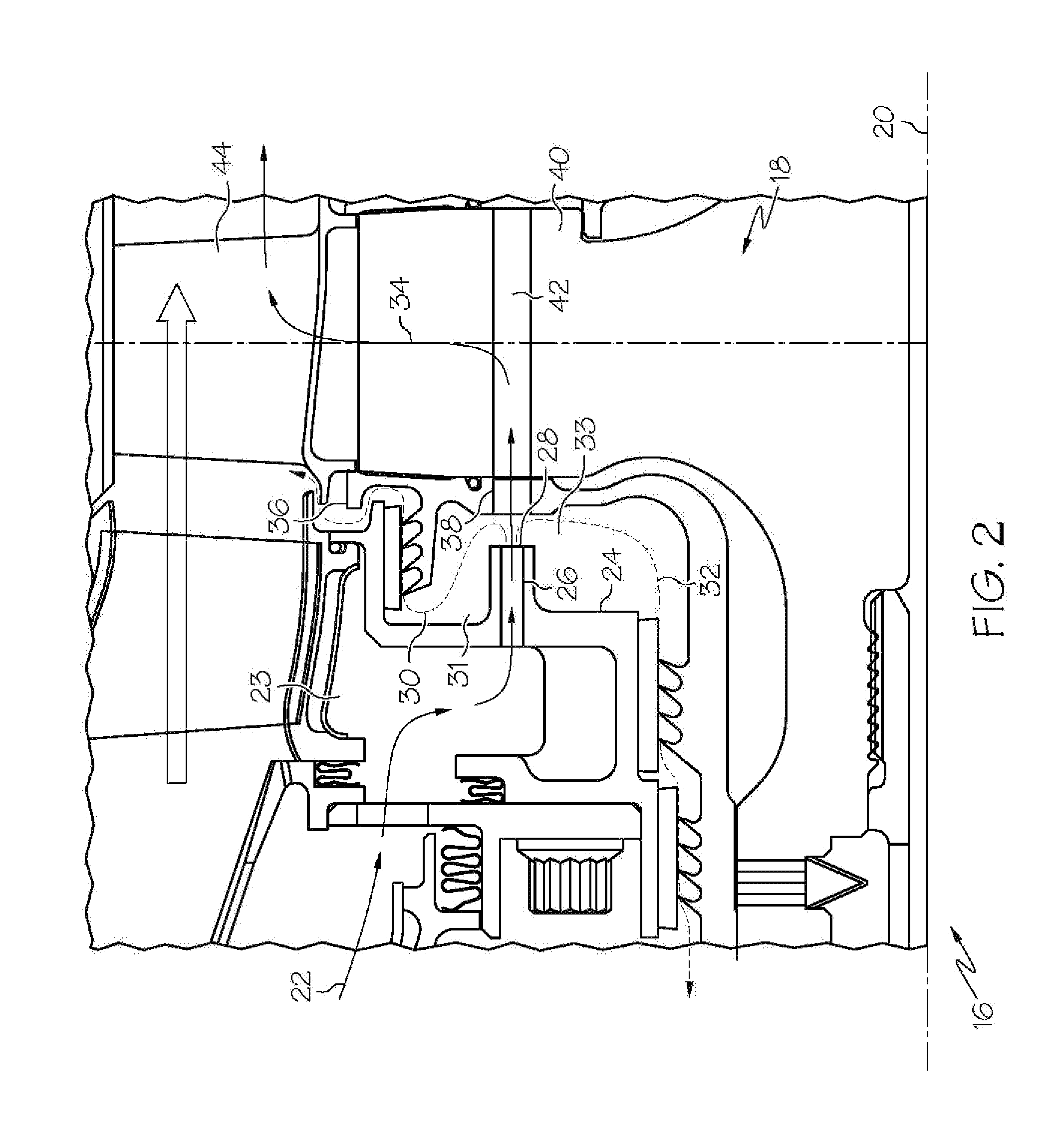
During operation, the turbine blades, the rotating disk, and other components of the turbine section may be exposed to elevated gas path temperatures, and thus may require cooling.
When the cooling air comes onboard the turbine rotor energy losses may occur resulting in a drop in pressure and a temperature increase.
However, gas turbine engines must be designed such that the use of secondary airflow is minimized, as that secondary cooling flow is diverted from the main core flow and does not do any actual work in the upstream turbine stages where it is dumped.
The challenge lies in transferring the air from the static structure to the rotating components while minimizing the pressure drop and temperature increase.
A primary weakness with the radial TOBI is that by pumping the cooling air to a higher radius where the blade slot bottom resides, as in a centrifugal compressor, the temperature of the air is raised significantly and the swirl ratio is lowered by the time it reaches the blade.
In that there is no pressure recovery, the maximum TOBI swirl ratio is limited and leakages are higher.
This is necessary due to the high rotational speeds and high disk stresses.
A direct transfer TOBI is the most favorable configuration in terms of minimizing secondary cooling flow and maximizing turbine efficiency, however this type of configuration is not feasible for small, high-performance turbines due to the inherent high rotor stresses precluding rotor holes feeding the blade slots.

Method used


Image

  • Direct transfer axial tangential onboard injector system (TOBI) with self-supporting seal plate
  • Direct transfer axial tangential onboard injector system (TOBI) with self-supporting seal plate
  • Direct transfer axial tangential onboard injector system (TOBI) with self-supporting seal plate

Examples


Embodiment Construction

[0023]Before proceeding with the description, it is to be appreciated that the following detailed description is merely exemplary in nature and is not intended to limit the invention or the application and uses of the invention. Furthermore, there is no intention to be bound by any theory presented in the preceding background or the following detailed description.

[0024]The embodiment disclosed herein is described in sufficient detail to enable those skilled in the art to practice the invention, and it is to be understood that other embodiments may be utilized and that logical mechanical changes may be made without departing from the scope of the present invention. Furthermore, it will be understood by one of skilled in the art that although the specific embodiment illustrated below is directed at the cooling of turbine blades point which is diametrically opposite another point on a sphere of a gas turbine engine in an aircraft, for purposes of explanation, the apparatus may be used ...


PUM


Abstract

An apparatus for cooling turbine blades in a turbine engine including a direct transfer axial tangential onboard injector (TOBI) for a turbine rotor and a self-supporting seal plate disposed on a rotating disk for the turbine engine. The TOBI includes a plurality of openings emanating a flow of cooling air. The self-supporting seal plate comprises a plurality of shaped cooling holes in fluid communication with the flow of cooling air emanating from the TOBI. The rotating disk includes a plurality of turbine blade slots formed therein. The plurality of cooling holes are in fluid communication with the plurality of turbine blade slots for directing the flow of cooling air to provide cooling to the plurality of turbine blades. The plurality of openings, the plurality of cooling holes and the plurality of turbine blade slots are in axial alignment and optimized to minimize radial and hoop stresses.

Description

STATEMENT REGARDING FEDERALLY SPONSORED RESEARCH OR DEVELOPMENT[0001]This invention was made with Government support under W911W6-08-2-0001 awarded by U.S. Army. The Government has certain rights in this invention.TECHNICAL FIELD[0002]The present invention generally relates to an apparatus for providing a cooling flow to a high pressure turbine rotor. More specifically, the present invention relates to an apparatus relating to providing a cooling flow to a turbine rotor by controlling the alignment and geometry of a plurality of cooling holes formed in the engine assembly and a cooperating seal plate.BACKGROUND[0003]Turbine engines may include a compressor section, wherein inlet air is compressed, followed by a combustor section wherein fuel is combusted with the compressed air to generate exhaust gas. The exhaust gas is then directed to a turbine section, wherein energy is extracted from the exhaust gas.[0004]The turbine section may comprise a rotor assembly. The rotor assembly may...

Claims


Application Information

Patent Timeline
Patent Type & Authority Applications(United States)
IPC IPC(8): F02C7/18
CPCF01D5/081Y02T50/676Y02T50/673F02C7/18Y02T50/60
Inventor SMOKE, JASONMITLIN, BOBMIRZAMOGHADAM, ALEXANDER
Owner HONEYWELL INT INC
Learn More