Cooling system for a battery system and a method for cooling the battery system

a battery system and cooling system technology, applied in the field of a cooling system for a battery system, can solve the problem of not being able to maintain the battery cells within the desired temperature range in an air-cooled battery pack, and achieve the effects of reducing the temperature level of the first battery module, dissipating heat energy, and reducing the temperature level

Inactive Publication Date: 2010-11-04
LG CHEM LTD
View PDF112 Cites 73 Cited by
  • Summary
  • Abstract
  • Description
  • Claims
  • Application Information

AI Technical Summary

Benefits of technology

[0005]A cooling system for a battery system in accordance with an exemplary embodiment is provided. The cooling system includes a housing having a first enclosed portion and a second enclosed portion. The first enclosed portion is configured to receive a first battery module therein. The cooling system further includes a first evaporator disposed in the first enclosed portion. The cooling system further includes a first evaporator fan disposed proximate to the first evaporator in the first enclosed portion configured to recirculate air in a first closed flow path loop within the first enclosed portion. The first evaporator is configured to extract heat energy from the air in the first closed flow path loop to reduce a temperature level of the first battery module. The cooling system further includes a condenser disposed in the second enclosed portion and fluidly coupled to the first evaporator. The condenser is configured to receive heat energy in a refrigerant from the first evaporator and to dissipate the heat energy. The cooling system further includes a compressor disposed in the second enclosed portion that recirculates the refrigerant throu

Problems solved by technology

However, the typical air-cooled battery pack has a major challenge in maintaining a temperature of the battery pack within a desired temperat

Method used


Image

  • Cooling system for a battery system and a method for cooling the battery system
  • Cooling system for a battery system and a method for cooling the battery system
  • Cooling system for a battery system and a method for cooling the battery system

Examples


Embodiment Construction

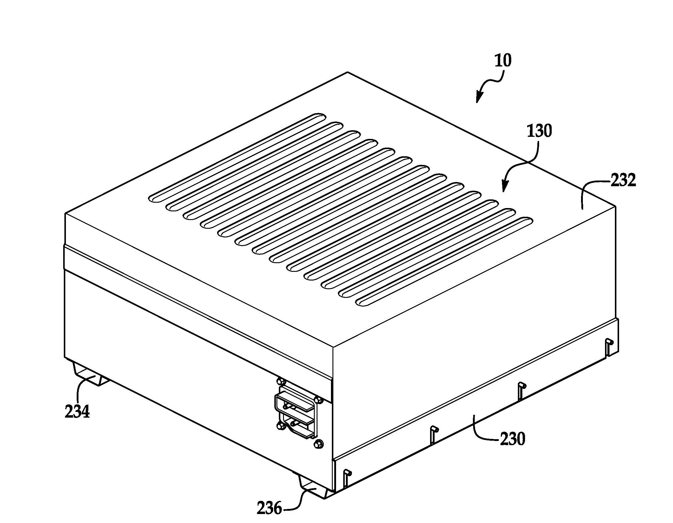
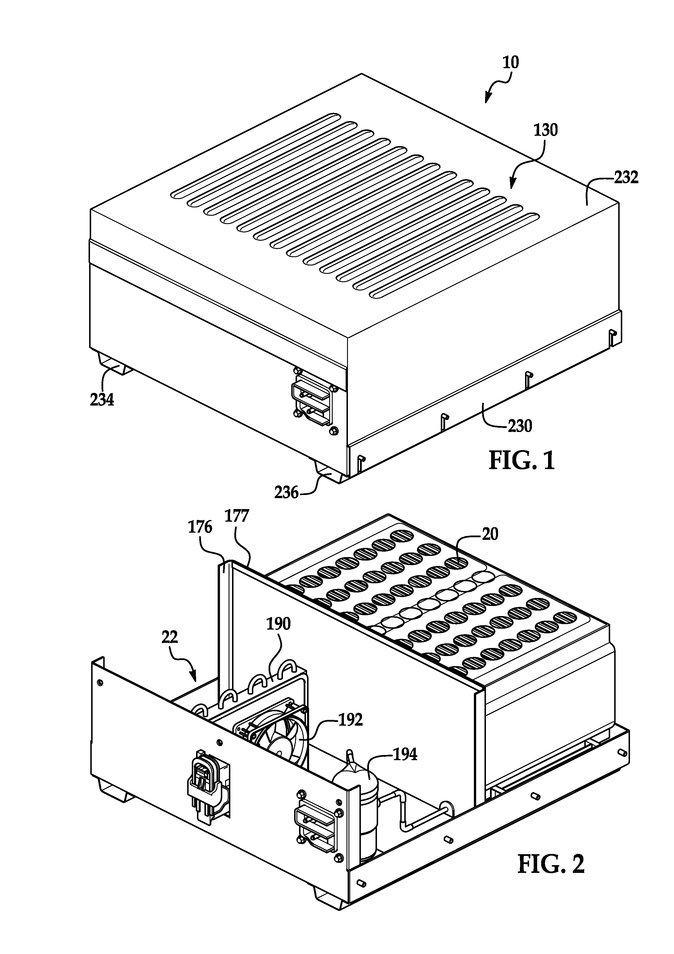
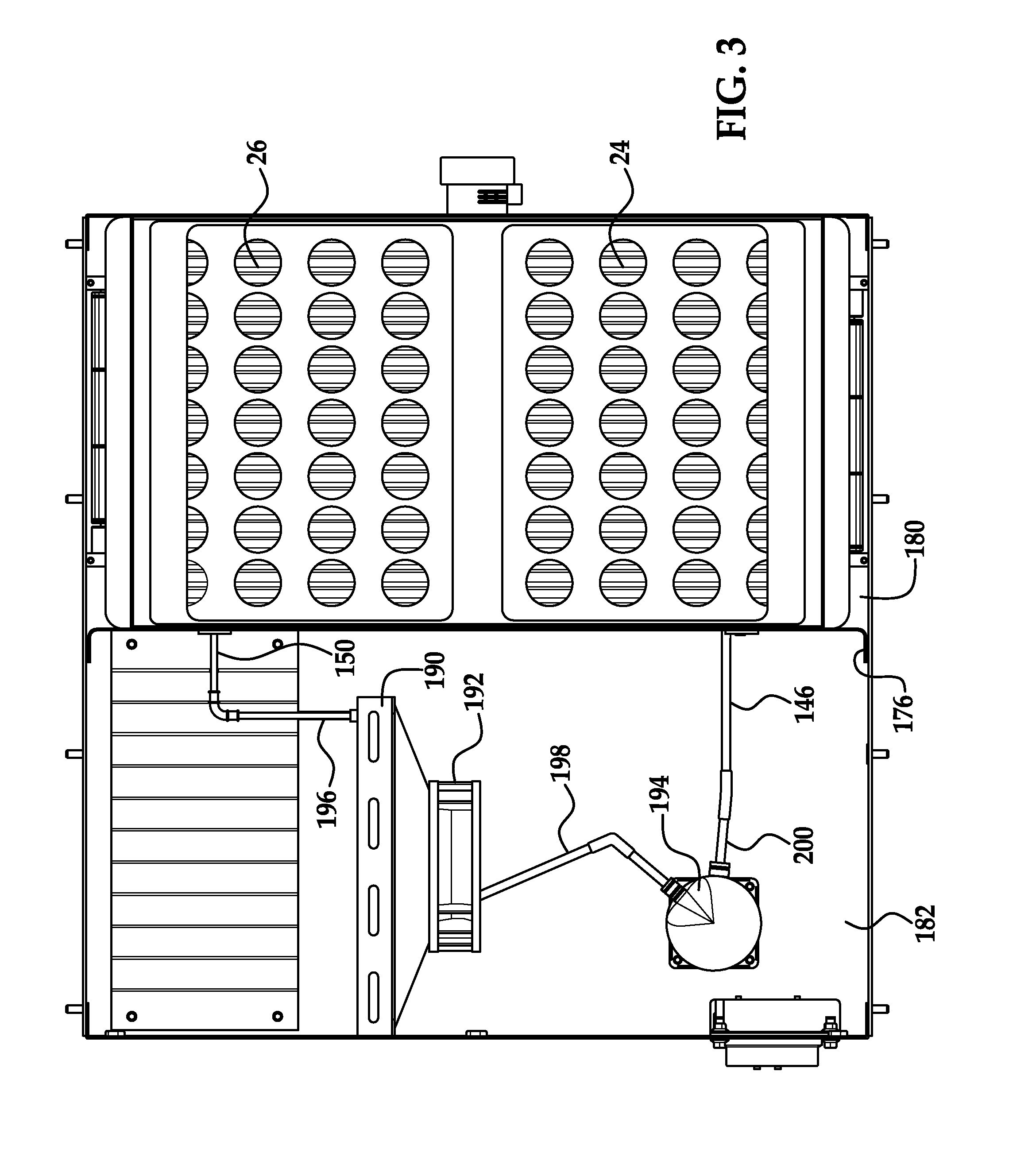
[0020]Referring to FIGS. 1-3, a power generation system 10 for outputting electrical power in accordance with an exemplary embodiment is illustrated. The power generation system 10 includes a battery system 20 and a cooling system 22.

[0021]The battery system 20 is provided to output electrical power. The battery system 20 includes the battery modules 24, 26. Each of the battery modules 24, 26 has a similar structure and includes a plurality of battery cell assemblies that can be electrically connected in series to one another or in parallel to one another. For purposes of brevity, only a portion of the battery cell assemblies in the battery module 24 will be described in detail. For example, referring to FIGS. 8-10, the battery module 24 includes battery cell assemblies 28, 29, 30, 31, 32, 33, 34, 36, 38, 40 and 42 and flow channel manifolds 60, 62, 64, 66, 68, 70, 72, 74, 76 and 78. Each of the battery cell assemblies has a battery cell therein that generates an operational voltage...


PUM


Abstract

A cooling system for a battery system and a method for cooling the battery system are provided. The cooling system includes a housing having first and second enclosed portions, and a first evaporator and a first evaporator fan disposed in the first enclosed portion that recirculates air in a first closed flow path loop within the first enclosed portion. The first evaporator extracts heat energy from the air in the first closed flow path loop to reduce a temperature level of a first battery module in the first enclosed portion. The cooling system further includes a condenser disposed in the second enclosed portion and fluidly coupled to the first evaporator, which receives heat energy in a refrigerant from the first evaporator and dissipates the heat energy. The cooling system further includes a compressor disposed in the second enclosed portion that recirculates the refrigerant through the first evaporator and the condenser.

Description

TECHNICAL FIELD[0001]This application relates to a cooling system for a battery system and a method for cooling the battery system.BACKGROUND OF THE INVENTION[0002]In a typical air-cooled battery pack, ambient air from ambient atmosphere is directed across battery cells in the battery pack and is subsequently exhausted from the battery pack. However, the typical air-cooled battery pack has a major challenge in maintaining a temperature of the battery pack within a desired temperature range.[0003]In particular, a maximum operating temperature of the battery cells can often be less than a temperature of ambient air utilized to cool the batteries. In this situation, it is impossible to maintain the battery cells within a desired temperature range in an air-cooled battery pack.[0004]Accordingly, the inventors herein have recognized a need for an improved battery cell assembly that minimizes and / or eliminates the above-mentioned deficiency.SUMMARY OF THE INVENTION[0005]A cooling system f...

Claims


Application Information

Patent Timeline
IPC IPC(8): F25B7/00H01M50/209
CPCF25D29/00F25D2317/0682F25D2700/16H01M10/486H01M10/633H01M10/6563H01M10/6569H01M10/613Y02E60/10H01M50/209
Inventor KOETTING, WILLIAMPAYNE, JOSHTOM, KWOK
Owner LG CHEM LTD
Why Eureka
Try Eureka