Punching unit

a technology of punching unit and punching hole, which is applied in the field of punching units, can solve the problems of difficulty in aligning punching and die, affecting the quality of punching holes, and increasing the product cost, and achieves the effect of simple and compact configuration and steady discharg

Inactive Publication Date: 2010-11-04
DAIDO KOGYO CO LTD
View PDF12 Cites 4 Cited by
  • Summary
  • Abstract
  • Description
  • Claims
  • Application Information

AI Technical Summary

Benefits of technology

[0017]According to the invention described above, the frames support the both ends of the punch shaft and die shaft and the very punch shaft and die shaft compose the structural members (reinforcing members) of the punching unit and no die frame and punch frame that have been otherwise necessary in the past is required, so that the punch shaft and die shaft may be readily removed and an engaging clearance (alignment) may be readily controlled. Still more, diameters of the punch shaft and die shaft may be enlarged and rigidity thereof may be increased. It allows high quality punch holes to be perforated regardless of types of the sheets. Further, because the hollow section is formed in the die shaft and the punch chip transporter is provided in the hollow section to transport and discharge the punch chips, it becomes possible to prevent the punch chips from clogging within the die and die shaft and to discharge the punch chips to a predetermined place altogether without scattering.
[0018]Because the punch shaft has the hollow section substantially across the whole length of the punch shaft and the punch shaft and die shaft are formed of a light alloy metal, the punch shaft and die shaft may be structured in high rigidity while having a light weight, thus allowing the quality of punch holes to be improved and the speed of the punching unit to be increased.
[0020]Further, because the guide is composed of the screw member fixed to the frame, the punch chips may be steadily discharged by relatively rotating the die shaft and the screw member without providing a driving source dedicated only for the screw member.
[0021]Still more, because the guide is composed of the screw structure disposed within the inner peripheral surface of the die shaft and rotated in a body with the die shaft, the punch chips may be transported and discharged by the simple and compact configuration.

Problems solved by technology

Although it has been possible to reduce a number of parts and a number of assembling processes of the punching unit described above, as compared to what has been constructed by a punch frame and a die frame by assembling a large number of plate members, because the punch shaft and the die shaft have been stored in the punch frame and die frame that are integrally formed members, it has been difficult to align the punch and die and to adequately control an engaging clearance because the punch frame and die frame have been integrally formed.
It has been also difficult to fully assure rigidity of these punch shaft and die shaft, coupled with that an outer dimension of the punching unit is limited, so that there has been a case when the engaging clearance varies depending on a thickness of the sheets, thus punching inferior holes in quality.
Still more, because the punching unit described above has required the punch frame and die frame having the closed section, a number of parts and an assembly time have increased by that much, causing an increase of the product cost.
Further, the punch chips scraped out by the discharging bar could not have been fully discharged by a method of discharging the punch chips out of the punch chip discharging port by leaving the natural fall.

Method used


Image

  • Punching unit
  • Punching unit
  • Punching unit

Examples


first embodiment

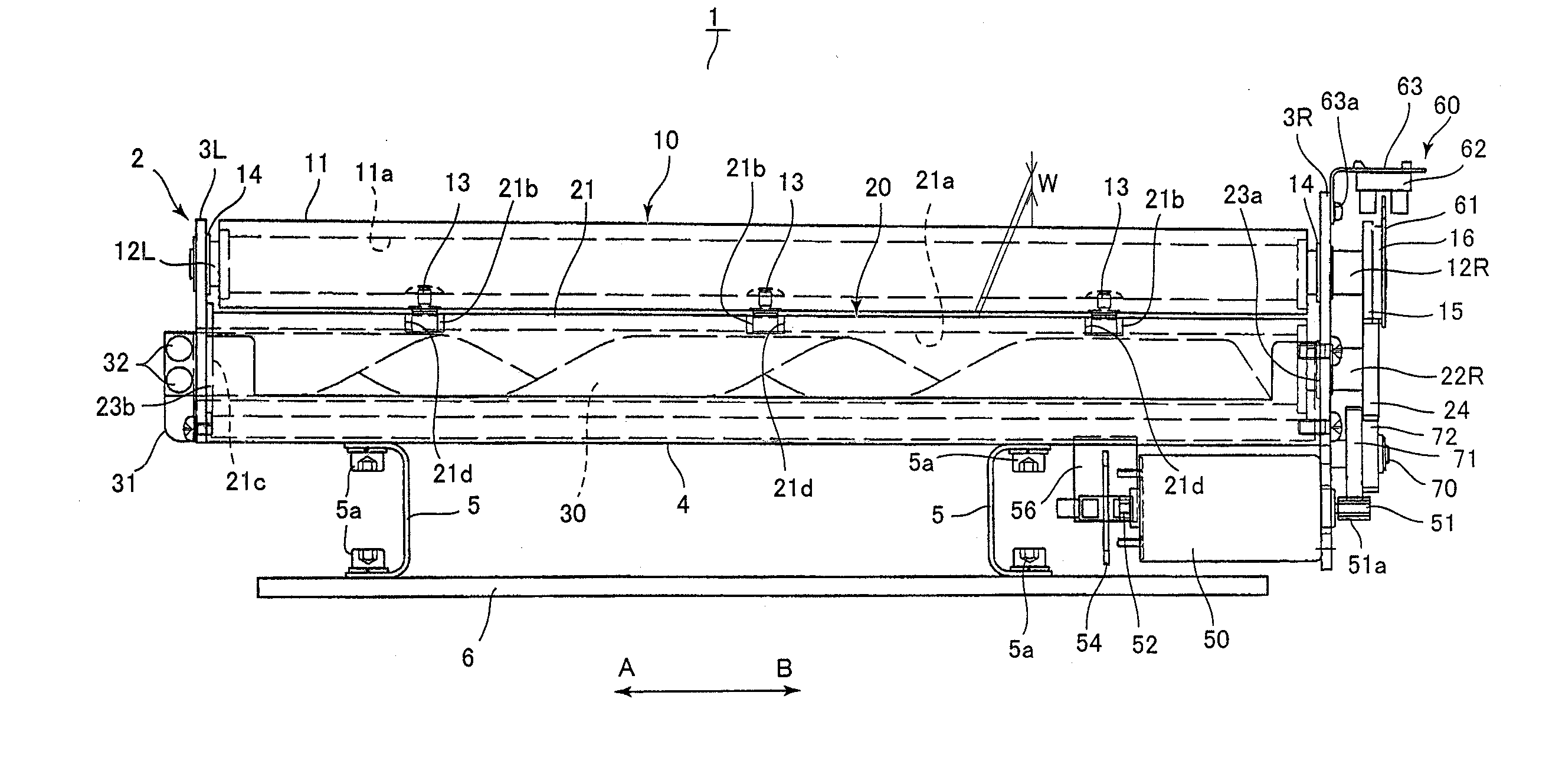
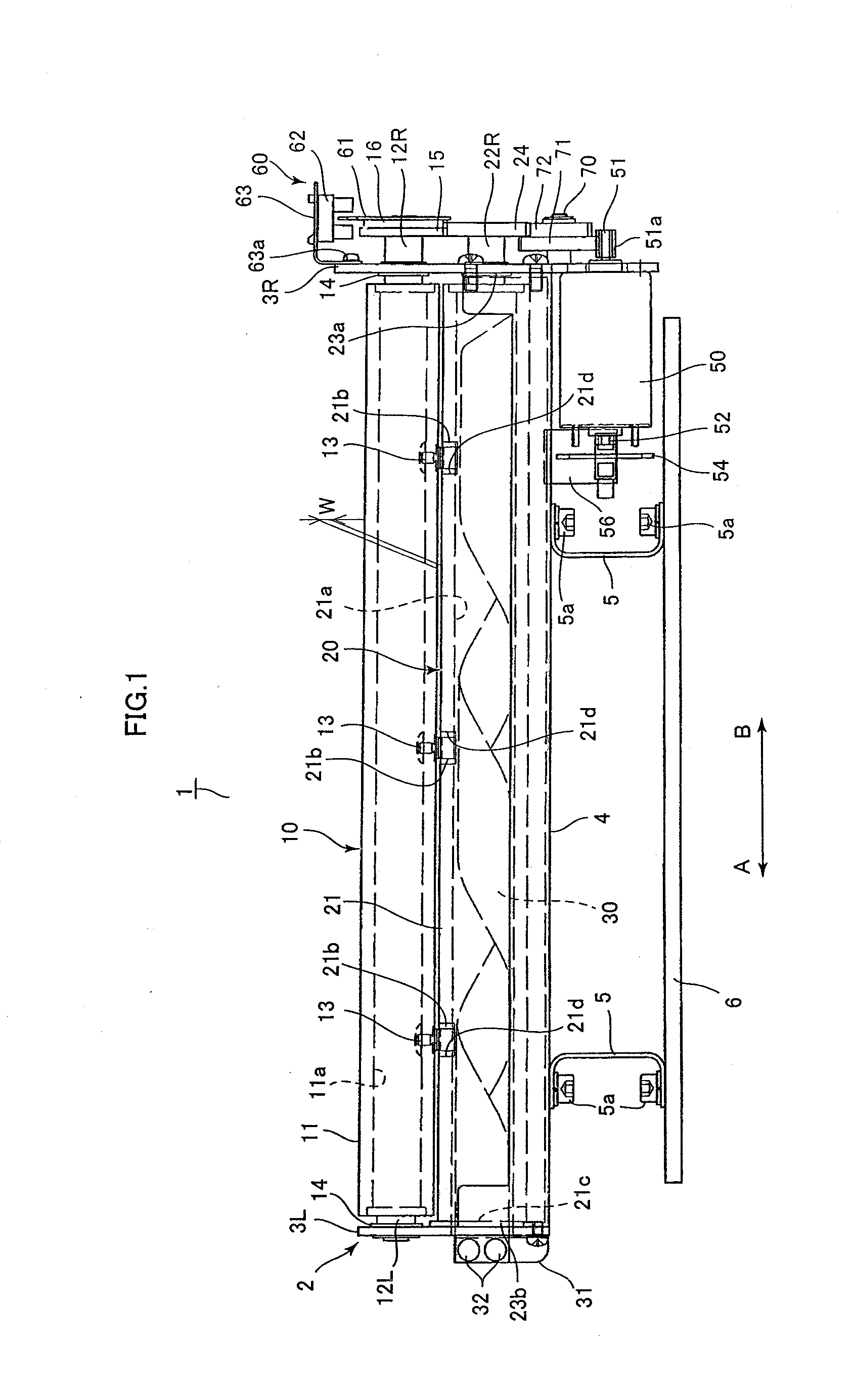
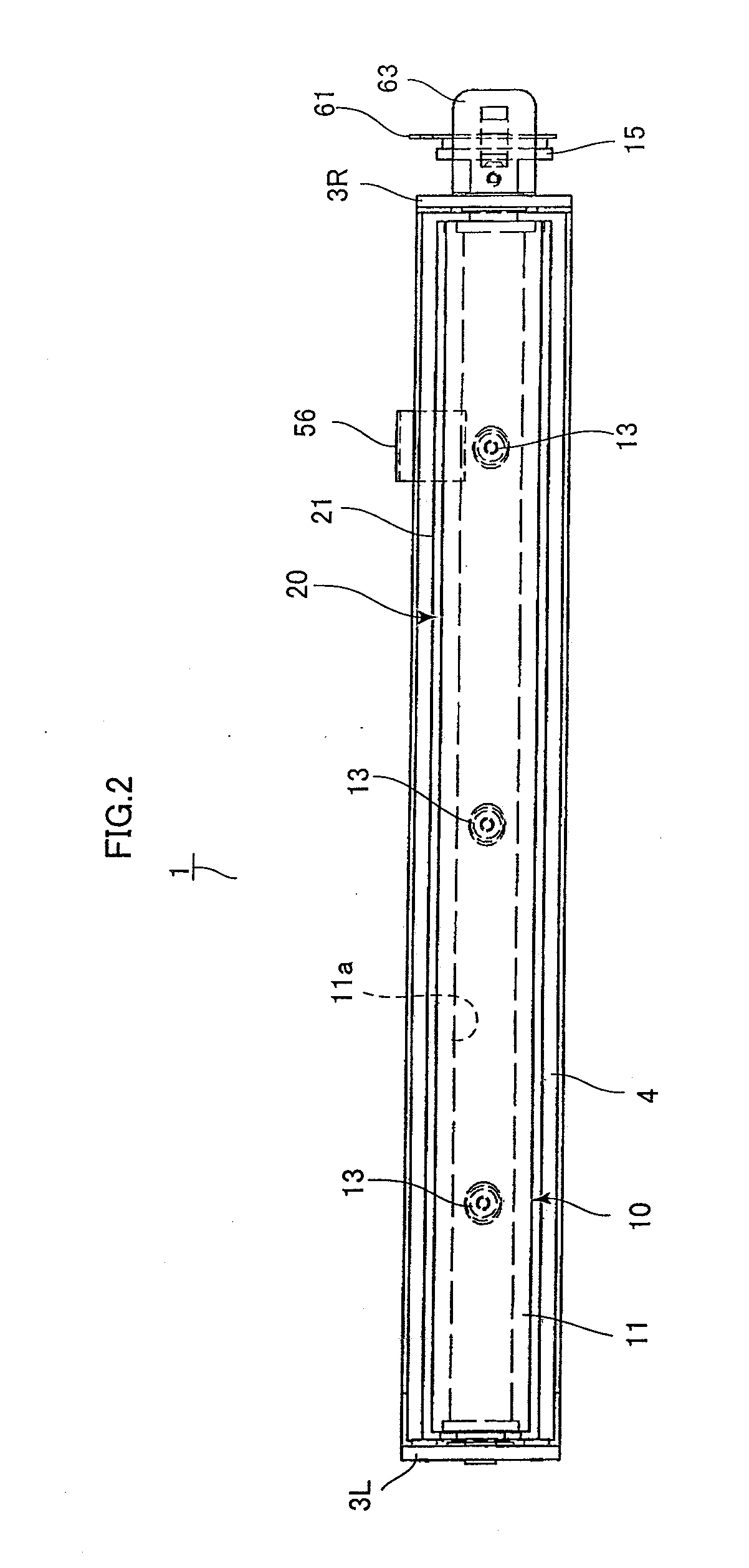
[0033]FIG. 1 is a front view, FIG. 2 is a plan view and FIG. 3 is a right side view of the punching unit 1 according to a first embodiment of the invention. As shown in FIGS. 1 through 3, the punching unit 1 has a pedestal 6 that is to be fixed to a frame of an image forming apparatus (having a post-processing device) such as a printer. The pedestal 6 is provided with a bottom plate 4 fixed thereto by bolts 5a through legs 5. The bottom plate 4 is provided with right and left side plates 3R and 3L on right and left ends thereof. A frame 2 is composed of the bottom plate 4 and the side plates 3R and 3L combined in a body. The side plates 3R and 3L support a punch shaft 10 and a die shaft 20 disposed in parallel between them so as to be rotatable. Together with the frame 2 described above, the punch shaft 10 and the die shaft 20 compose structural members (reinforcing members) of the punching unit 1. It is noted that the side plates 3R and 3L support the punch shaft 10 and die shaft 2...

second embodiment

[0052]FIGS. 4 and 7B shows a punching unit of a second embodiment of the invention. This embodiment is what the punch chip discharging screw plate 30 fixed in the first embodiment is substituted with a round rod formed so as to have spiral blades and is disposed integrally with the hollow section 21a of the die shaft 20. The parts different from the structure of the first embodiment will be explained below.

[0053]As shown in FIGS. 4 and 7A, a chip discharging screw rod 80 (guide or screw structure), i.e., a punch chip transporter, is a round rod formed so as to have the spiral blades and is attached integrally and fittingly within the hollow section 21a of the die shaft body 21. Therefore, when the die shaft 20 rotates, the chip discharging screw rod 80 rotates in a body with the inner peripheral surface of the hollow section 21a of the die shaft body 21 and the punch chips are discharged out of the opening 21c along the slopes of the blades of the chip discharging screw rod 80 based...

third embodiment

[0057]FIGS. 5, 6 and 7C shows a third embodiment of the invention. This embodiment is what the chip discharging screw plate 30 fixed in the first embodiment is modified into a coil-like member and the coil-like member is driven by the motor. The parts different from the structure of the first embodiment will be explained below.

[0058]As shown in FIGS. 5, 6 and 7C, a punch chip discharge coil (guide or screw member) 90, i.e., the punch chip transporter, is formed by winding a metal wire or a plastic flexible member into a cylindrical shape and a driving gear 94 is attached to one end thereof. The chip discharging coil 90 is disposed within the hollow section 21a of the die shaft body 21 in the direction from the arrow A to the arrow B in FIG. 5 and the driving gear 94 is rotatably supported by the side portion of the left side plate 3L.

[0059]The bottom plate 4 under the left side plate 3L is provided with a bracket 93 attached thereto by screws 93a to hold a chip discharging motor 91 ...


PUM

PropertyMeasurementUnit
lengthaaaaaaaaaa
thicknessaaaaaaaaaa
diametersaaaaaaaaaa

Abstract

There is provided a punching unit that is readily adjusted, is capable of always punching high quality holes through sheets and is steadily capable of discharging punch chips. A punch shaft and a die shaft are disposed vertically in parallel between side plates and these very punch shaft and the die shaft compose structural members (reinforcing members) of the punching unit. The die shaft has a die shaft body formed into a hollow cylinder and is provided with dies that correspond to the punches of the punch shaft at an outer peripheral surface thereof while fitting into die holes penetrating to the hollow section. A chip discharging screw plate fixed to the right side plate is disposed in the hollow section of the die shaft. Punch chips are transported along slopes of the chip discharging screw plate and discharged out of an opening when the die shaft rotates.

Description

CROSS REFERENCE TO RELATED APPLICATIONS[0001]This application claims the foreign priority benefit under Title 35, United States Code §119(a)-(d) of Japanese Patent Application No. 2007-314940, filed on Dec. 5, 2007 in the Japan Patent Office, the disclosure of which is herein incorporated by reference in its entirety.BACKGROUND OF THE INVENTION[0002]1. Field of the Invention[0003]The present invention relates to a punching unit mounted in image forming apparatuses such as a copier and a printer for punching holes through sheets (such as sheets of papers) on which images have been recorded.[0004]2. Related Art[0005]Heretofore, there have been proposed punching units for punching holes through sheets by rotating a punch shaft and a die shaft disposed in parallel from each other and respectively having a plurality of punches and dies to engage the punches of the punch shaft with the dies of the die shaft as disclosed in Japanese Patent Application Laid-Open Nos. 2000-301492 and 2000-30...

Claims


Application Information

Patent Timeline
Patent Type & Authority Applications(United States)
IPC IPC(8): B26D7/18B26F1/08
CPCB26D7/18B26F1/10B26D5/32Y10T83/222Y10T83/7809Y10T83/9387
Inventor NISHIMURA, KAZUOMAJIMA, TOSHIYUKIICHIKAWA, MEGUMIISHII, SUSUMU
Owner DAIDO KOGYO CO LTD
Why Eureka
Try Eureka