

Fisheye lens
a technology of fisheye lens and lens body, applied in the field of fisheye lens, can solve the problems of lens resolution not being enough, lens difficulty in manufacturing, poor modulation transfer function characteristics, etc., and achieve the effect of desirable optical and mechanical properties
- Summary
- Abstract
- Description
- Claims
- Application Information
AI Technical Summary
Benefits of technology
Problems solved by technology
Method used
Image

Examples
first embodiment
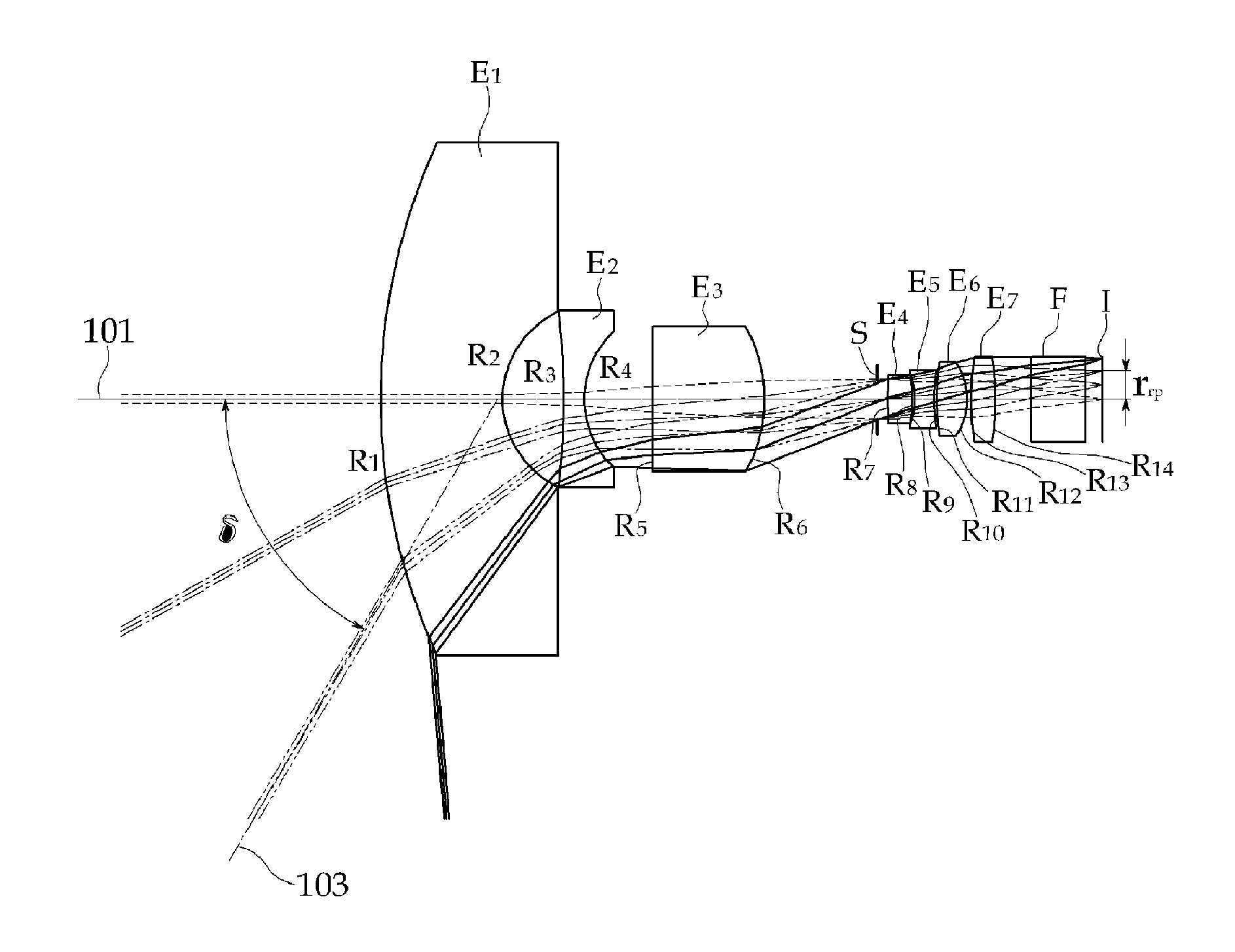
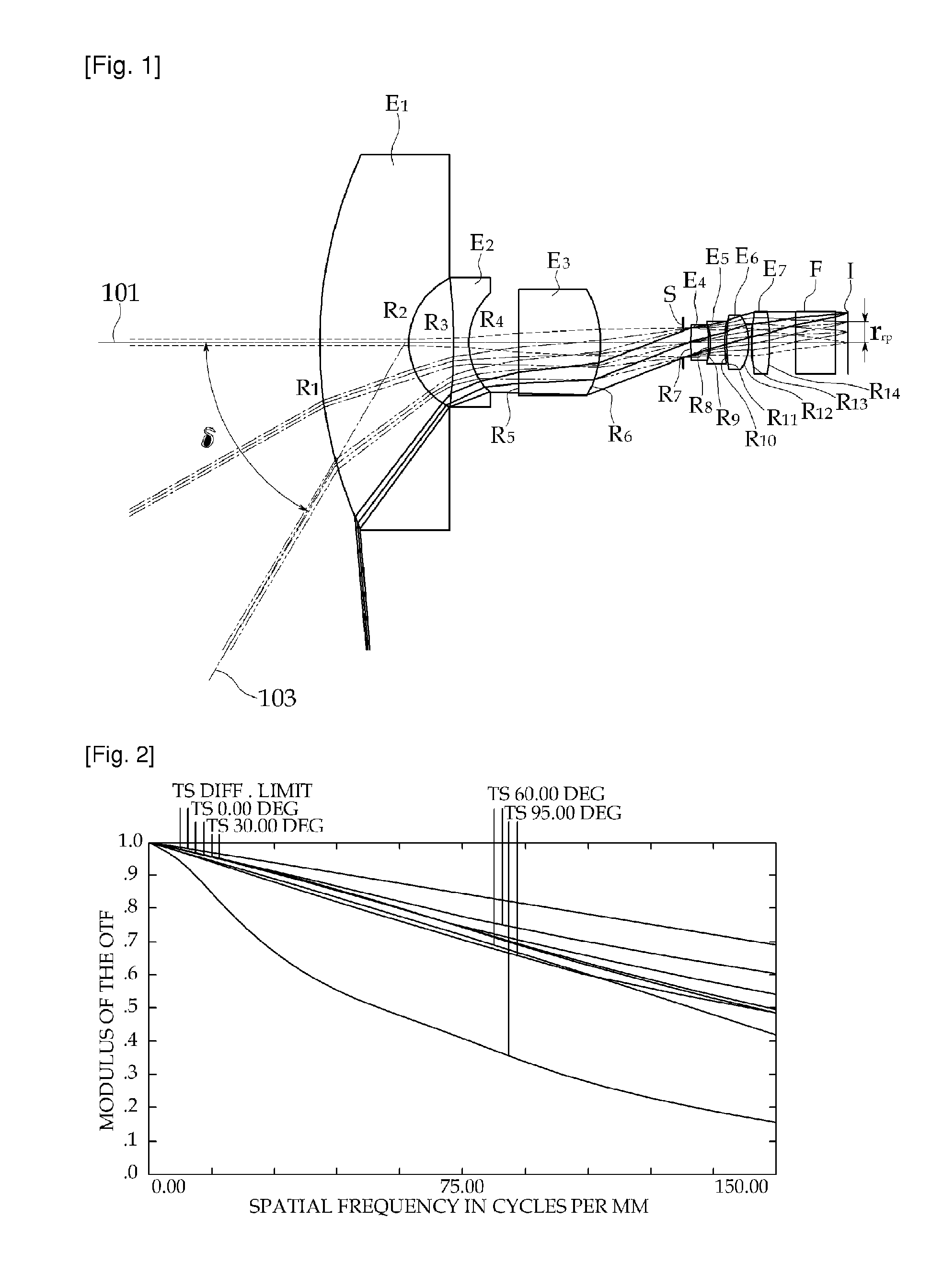
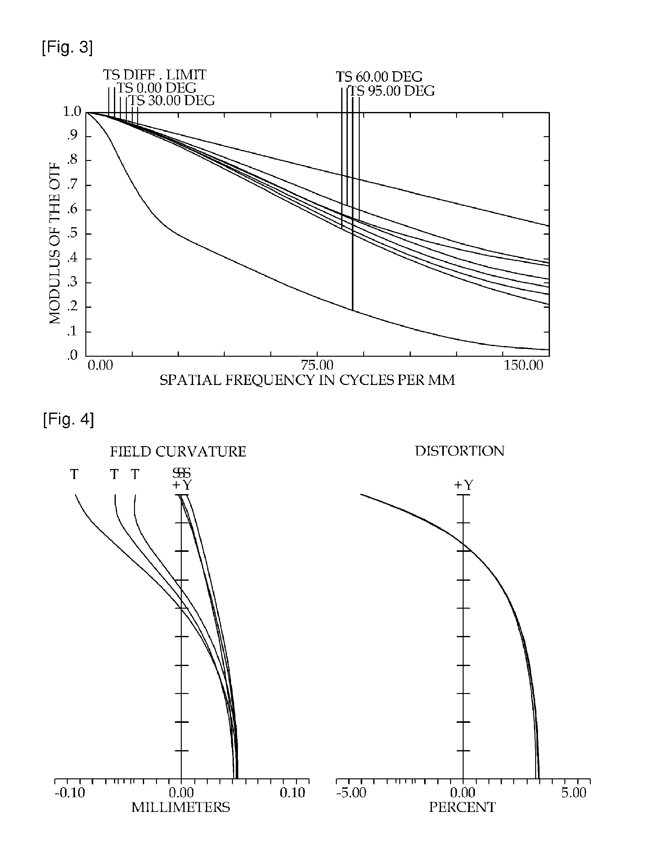
[0036]FIG. 1 shows the shape of the fisheye lens according to the first embodiment of the present invention and the ray trajectories. This lens is designed to work simultaneously in the visible and the near infrared wavelength ranges, and designed for a ⅓-inch CCD sensor with F-number of 2.8 and Field of view (FOV) of 190°. The lateral dimension of a ⅓-inch CCD sensor is 4.8 mm, the longitudinal dimension is 3.6 mm, and the diagonal dimension is 6.0 mm. In order to obtain a horizontal FOV of 180° or more from a camera using such an image sensor, the lens design is optimized so that the image height for an incidence angle of 90° is 2.35 mm.
[0037]This lens is comprised of the first lens element E1 through the seventh lens element E7, and the first through the seventh lens elements (E1˜E7) are all refractive lens elements with both lens surfaces being spherical surfaces. A stop S is located between the third lens element E3 and the fourth lens element E4. The optical low pass filter F ...
second embodiment
[0056]FIG. 6 shows the shape of the fisheye lens according to the second embodiment of the present invention and the ray trajectories. This lens is also designed to work simultaneously in the visible and the near infrared wavelength ranges, and designed for a ⅓-inch CCD sensor with F-number of 2.8 and Field of view (FOV) of 190°.
[0057]This lens is comprised of the first lens element E1 through the eighth lens element E8, and the first through the eighth lens elements (E1˜E8) are all refractive lens elements with both lens surfaces being spherical surfaces. A stop S is located between the fourth lens element E4 and the fifth lens element E5. An optical low pass filter F is located between the eighth lens element E8 and the image plane I. FIG. 6 shows that this lens has been designed with the optical low pass filter taken into account.
[0058]An incident ray originating from an object point on the object side has an incidence angle δ with respect to the optical axis of the lens. This in...
PUM
 Abstract
Description
Claims
Application Information