
Servo press and operating method thereof

Inactive Publication Date: 2010-11-11
IHI CORP
View PDF9 Cites 8 Cited by
  • Summary
  • Abstract
  • Description
  • Claims
  • Application Information

AI Technical Summary

Benefits of technology

[0014]The present invention is made by taking the circumstance mentioned above into consideration, and an object of the present invention is to provide a servo press which can obtain a higher speed in a moving section of a slide, and a higher pressure in a pressurizing section near a bottom dead point without enlarging a capacity of a motor. Further, an object of the present invention is to provide a servo press in which it is not necessary to interpose a plunger between a toggle mechanism and a slide. Further, an object of the present invention is to provide a servo press which can suppress a total height of an apparatus. Further, an object of the present invention is to provide an operating method of the servo press mentioned above.

Problems solved by technology

Accordingly, there is a problem that the motor is enlarged in size and a cost is increased.
In other words, there is a problem that the essentially unnecessary element is included.
In the press machine, it is required to secure a fixed stroke or more while suppressing the total height of the apparatus, however, in the servo press of Japanese Unexamined Patent Publication No. 2001-300778, there is a problem that it is hard to satisfy such a request.

Method used


Image

  • Servo press and operating method thereof
  • Servo press and operating method thereof
  • Servo press and operating method thereof

Examples


first embodiment

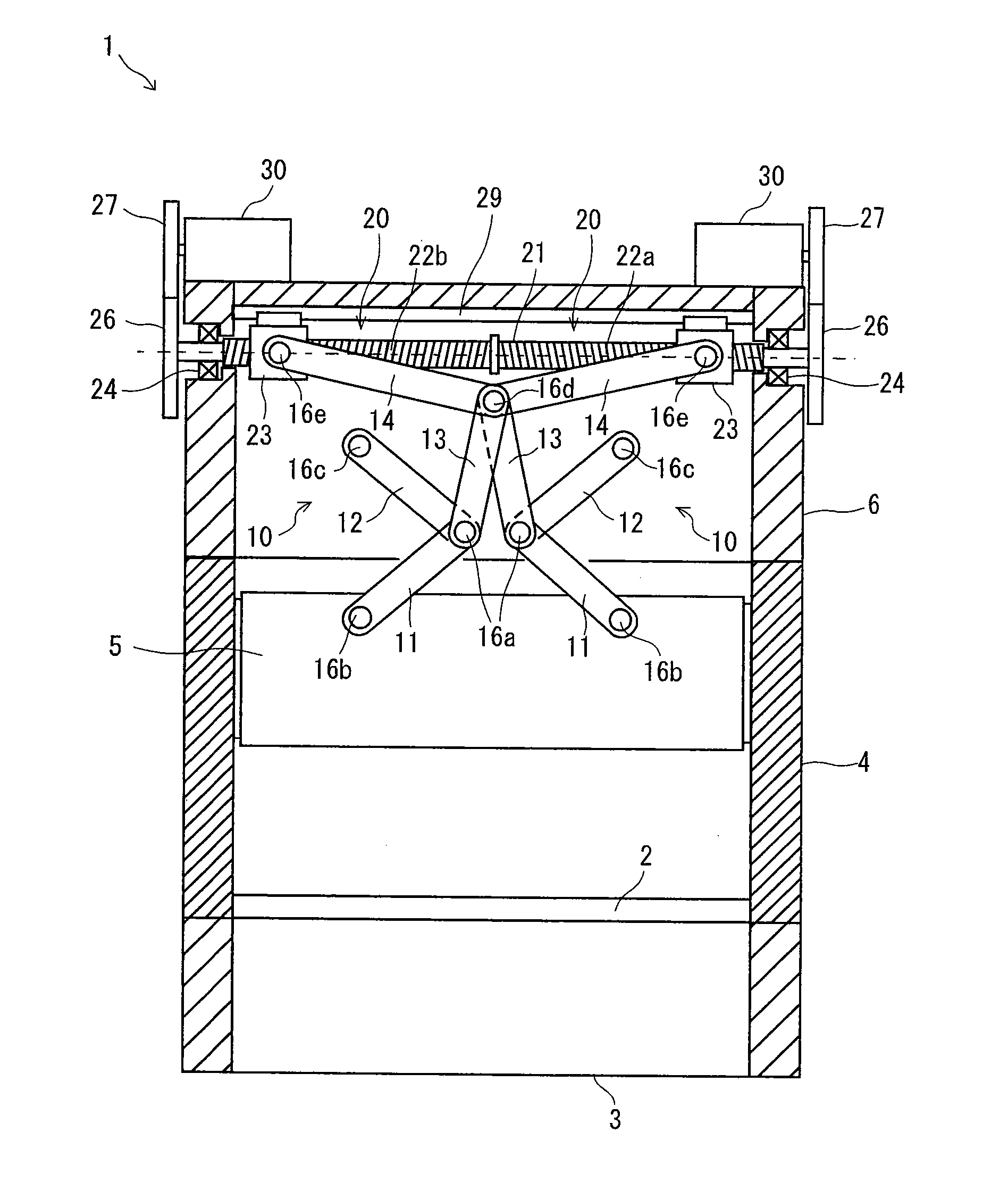
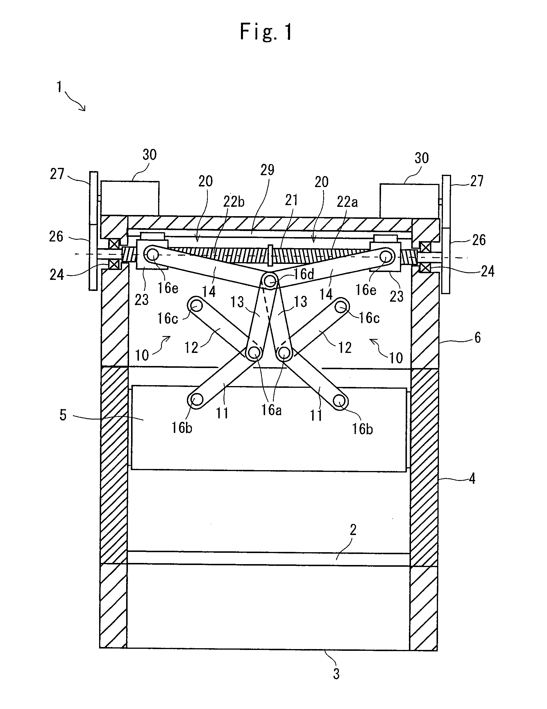
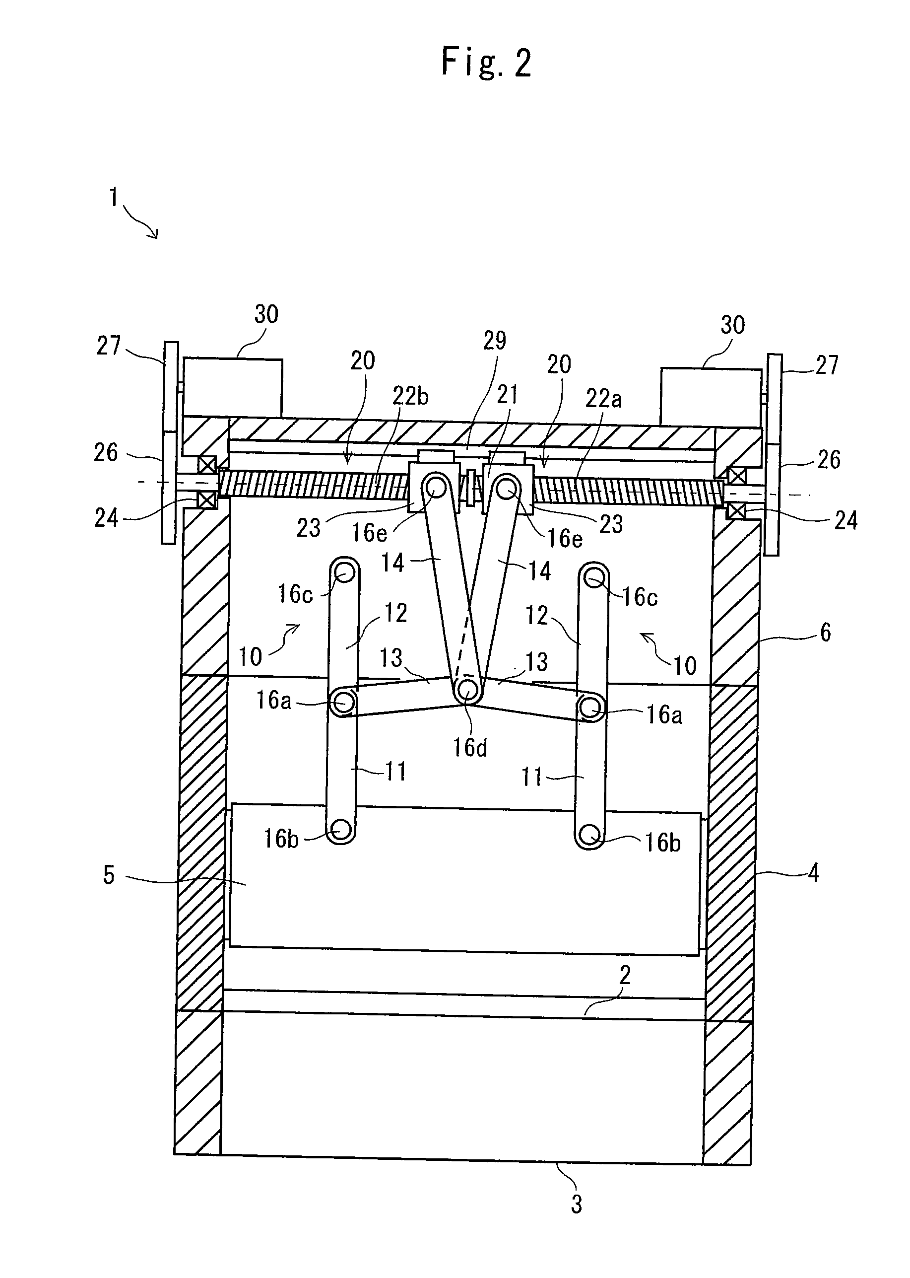
[0057]FIGS. 1 and 2 are views showing a structure of a servo press 1 in accordance with a first embodiment of the present invention. FIG. 1 shows a state in which a slide 5 exists at a top dead point position, and FIG. 2 shows a state in which the slide 5 exists at a bottom dead point position. FIG. 3 is a plan view of the servo press 1 in FIG. 1.

[0058]In FIG. 1, in the servo press 1, a column 4 (also called as an upright) is provided in a rising manner on a bed 3 in which a bolster 2 is fixed to an upper portion, and a crown 6 is provided on the column 4. The slide 5 is supported to the column 4 so as to be slidable up and downs. A lower die (not shown) is to be fixed to an upper surface of the bolster 2, and an upper die (not shown) is to be fixed to a lower surface of the slide 5.

[0059]Further, the servo press 1 is provided with a multi-toggle mechanism 10 moving up and down the slide 5, a toggle driving mechanism 20 driving the multi-toggle mechanism 10, and a servo motor 30 dri...

second embodiment

[0101]FIG. 10 is a view showing a structure of a servo press 1 in accordance with a second embodiment of the present invention.

[0102]The servo press 1 in accordance with the present embodiment is provided with a pair of multi-toggle mechanisms 10 which are symmetric in the drawing, and a pair of toggle driving mechanisms 20 which are symmetric in the drawing, in the same manner as the first embodiment.

[0103]In the first embodiment mentioned above, the feed screw shaft 21 with which the nut member 23 is engaged is constituted by one common screw shaft, however, in the present embodiment, each of the nut members 23 is engaged with each of independent feed screw shafts 21A. Each of the feed screw shafts 21A is supported by the bearing 24 so as to be rotatable around a horizontal axis.

[0104]Further, in the present embodiment, each of the feed screw shafts 21A is rotationally driven by two servo motors 30.

[0105]Further, in the first embodiment, one ends of respective fourth link 14 of th...

third embodiment

[0112]A description will be given of an operating method of the servo press 1 in accordance with the embodiment mentioned above in accordance with a third embodiment of the present invention, with reference to FIG. 11.

[0113]As mentioned above, since the servo press 1 in accordance with the present invention can obtain the higher speed in the moving section of the slide and the higher pressure in the pressurizing section near the bottom dead point, by employing the three-stage toggle, it is possible to achieve an excellent capability in the punching work.

[0114]In this case, when defining the stroke from the bottom dead point in the case of executing the work having a long pressurizing section such as a drawing work by the servo press having the three-stage toggle, in order to secure a pressing force over a whole of the pressurizing section, a large capacity motor is normally necessary. This is because the pressure is low while being at the high speed in the upper section than the por...


PUM


Abstract

The invention provides a servo press which can obtain a higher speed in a moving section of a slide, and a higher pressure in a pressurizing section near a bottom dead point without enlarging a capacity of a motor. The servo press is provided with a multi-toggle mechanism 10 moving up and down a slide 5 in which an upper die is to be fixed to a lower surface of the slide, and a toggle driving mechanism 20 provided on a crown 6 located to an upper side of the slide and driving the multi-toggle mechanism. The multi-toggle mechanism 20 is structured such as to include three or more toggles generating a force amplifying effect by a plurality of links 11, 12, 13, 14.

Description

BACKGROUND OF THE INVENTION[0001]1. Field of the Invention[0002]The present invention relates to a servo press moving up and down a slide by a toggle mechanism and an operating method thereof.[0003]2. Description of the Related Art[0004]Conventionally, there has been known a servo press having a toggle mechanism (also called as a knuckle mechanism). The toggle mechanism converts a linear motion taken out by converting a rotation of a servo motor, into an upward and downward motion of a slide.[0005]Generally, the toggle mechanism is provided with a first link and a second link in which one ends thereof are rotatably connected to each other in a connecting point, the other end of the first link is rotatably connected to a part of a crown, the other end of the second link is rotatably connected to the slide, and a driving link is rotatably connected to the connecting point between the first link and the second link.[0006]In the toggle mechanism having the structure mentioned above, sin...

Claims


Application Information

Patent Timeline
IPC IPC(8): B30B1/10B30B1/18
CPCB30B1/106B30B1/103B30B1/02B30B1/10B30B1/18B30B15/06
Inventor YAMASAKI, SHUSAKU
Owner IHI CORP
Features
  • Generate Ideas
  • Intellectual Property
  • Life Sciences
  • Materials
  • Tech Scout
  • Unparalleled Data Quality
  • Higher Quality Content
  • 60% Fewer Hallucinations
Learn More