Foldable ramp for missile launchers

a missile launcher and folding technology, applied in missile launchers, offensive equipment, weapons, etc., can solve the problems of aft flame of the launch device, damage to the platform, and not always the case, so as to reduce radar and eye visibility of the launcher

Active Publication Date: 2010-11-11
ONUK TASIT SANAYI SIRKETI
View PDF20 Cites 28 Cited by
  • Summary
  • Abstract
  • Description
  • Claims
  • Application Information

AI Technical Summary

Benefits of technology

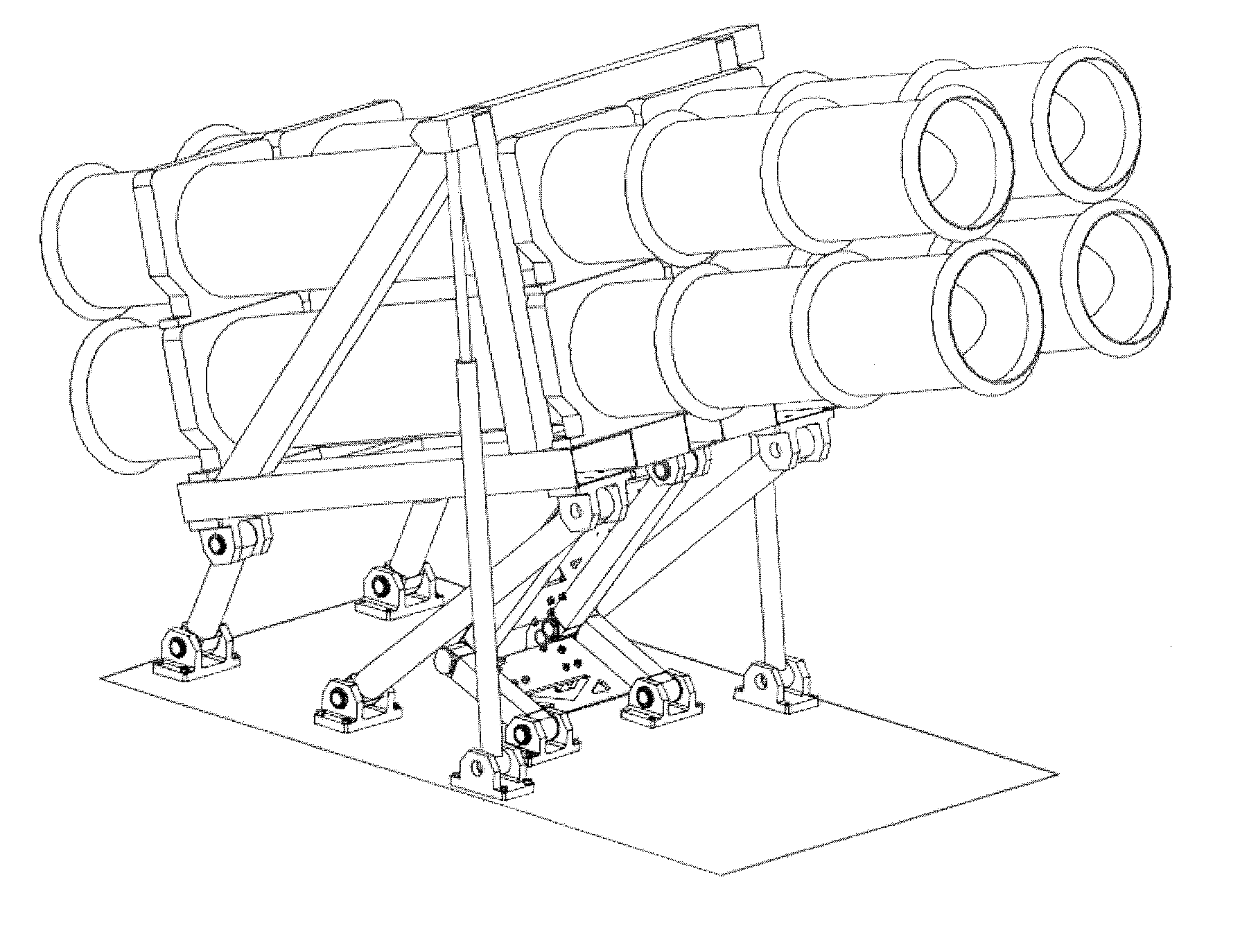
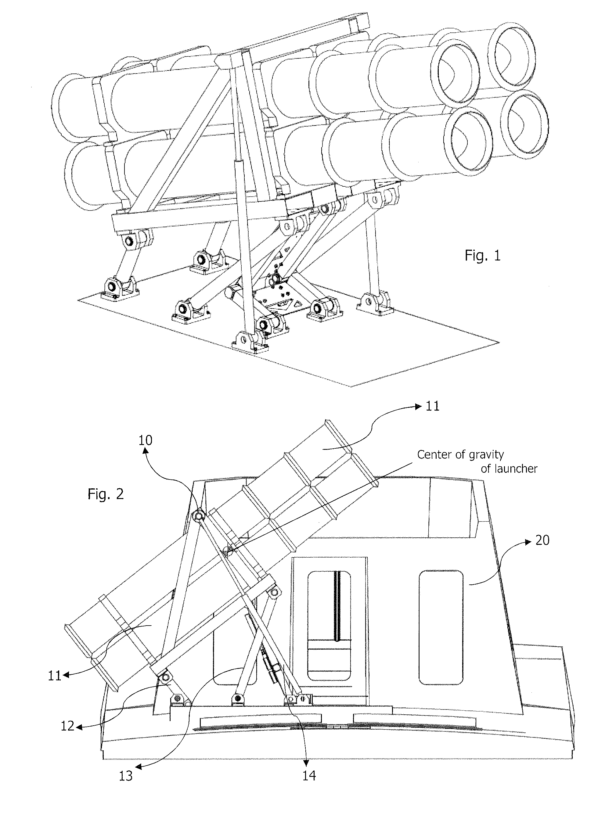
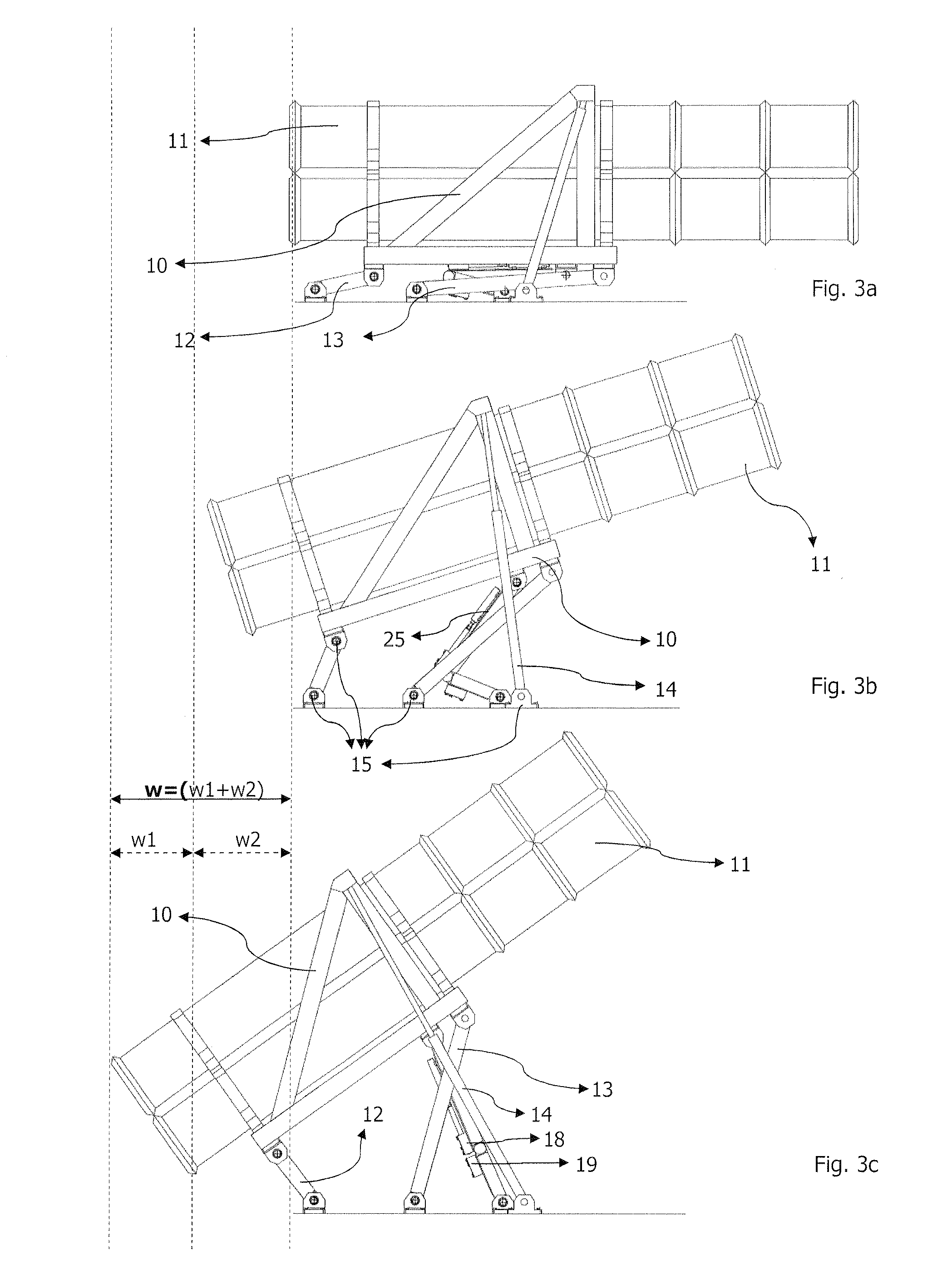
[0006]The foldable ramp is intended to store, carry and launch relatively large size tube-launched missiles typically on board of relatively small sized naval surface ships. Accordingly, the foldable ramp according to the present invention comprises a frame suitable for carrying one or more canisters for launching rockets or missiles. The foldable ramp further comprises at least one rear support element and at least one front support elements, which are pivotably attached to the frame and which are adapted to pivotably connect to the launching platform so as to allow rotary movement of the frame with respect to the launching platform. A lifting device lifts the front end of the frame whereby the rear end of the canisters displace a horizontal distance towards the rear of the ramp as said lifting device lifts the front end of said frame. Adverse effects of the aft flame of the launched rocket or missile is therefore securely displaced to the outside of the vehicle to which the foldable ramp of the present invention is installed. Furthermore, the foldability of the ramp along with the side features enables to prevent or at least to reduce radar and eye visibility of the launcher, particularly when mounted on a naval surface ship.

Problems solved by technology

Nevertheless, this is not always the case e.g. for unguided rocket launchers.
A major drawback of this type of a ramp is the damage to the platform due to high heat release from nozzle of the drive source of the rocket or missile during launching.
The aft flame of the launched device is not only harmful for the surface of launching platform but also hazardous for any personnel that might be in the vicinity of the platform.
When a guided missile is to be launched from a naval surface ship, the aft flame of the missile becomes detrimental for the deck of the ship.
This requires special processing on the surface of the deck and adds cost when installing launchers on ships.
Still, the aft flame of the missile is hazardous for personnel in the proximity of the launcher platform on the deck.
While taller constructions help reduce the flame damage, they are generally very heavy which makes them impractical for use on frigates or relatively small sized surface ships, typically less than 50 m long.
Another problem associated with these conventional ramps is their enormous radar visibility, which makes them suitable for use only on large size destroyers.
While high speed frigates can be made to have a considerably low radar cross section, there is no effective solution that would allow them carry a relatively large launcher on board without jeopardizing their radar invisibility.
As conventional launchers have limited freedom of movement, where typically the canisters may only be rotated and pitched, their visibility on the deck still poses a potential risk even during piece time.
While visibility of missile launchers on board of a patrolling frigate may be scary or at least undesired for a friendly civilian, it is on the other hand fairly informative for the unfriendly ones in terms of the amount and type of the armament carried on the frigate.
Hence, conventional launchers not only have the drawback of unfavorable radar cross section, but also the drawback of eye visibility.

Method used


Image

  • Foldable ramp for missile launchers
  • Foldable ramp for missile launchers
  • Foldable ramp for missile launchers

Examples


Embodiment Construction

[0031]Hereinafter, preferred embodiments of the present invention will be described in detail with reference to the accompanying drawings which are given solely for the purpose of exemplifying embodiments according to the present invention.

[0032]Foldable ramp (1) according to the present invention comprises a frame (10) adapted to carry one or more canisters (11) from which rockets or missiles are launched. While the embodiment shown in the attached drawings exemplify a four canister holder, it is possible to increase or decrease the number of canisters carried and orientated by the frame member (10). The frame is carried by a rear support member (12) and a front support member (13), both of which are pivotably connected and hence movable with respect to the frame (10) as shown in FIGS. 4a to 4c. While the embodiment shown in the attached drawings illustrate the rear and front support members (12,13) in the form of two separate legs for each, it is still within the scope of the pres...


PUM


Abstract

The foldable ramp is intended to store, carry and launch relatively large size tube-launched missiles typically on board of relatively small sized naval surface ships. Accordingly, the foldable ramp comprises a frame suitable for carrying one or more canisters for launching rockets or missiles and support elements, which are pivotably attached to the frame and which are adapted to pivotably connect to the launching platform so as to allow rotary movement of the frame with respect to the launching platform. A lifting device lifts the front end of the frame whereby the rear end of the canisters displace a horizontal distance towards the rear of the ramp as said lifting device lifts the frame. Adverse effects of the aft flame of the launched rocket or missile is securely displaced to the outside of the vehicle while foldability of the ramp enables to prevent or reduce radar and eye visibility of the launcher, particularly when mounted on a naval surface ship.

Description

TECHNICAL FIELD OF THE INVENTION[0001]The present invention relates to a foldable ramp for missile launchers, particularly for use on relatively small sized military purpose surface ships. The foldable ramp as proposed by the present invention is particularly suitable for launching self propelled SAM type (surface-to-air) or SSM type (surface-to-surface) guided missiles from frigates.DESCRIPTION OF THE PRIOR ART[0002]Guided missiles are self propelled and guided internally or externally from a remote location such as a satellite or the launching station once the missile is fired from its ramp. The ramp is usually in the form of a plurality of canisters that are used to carry, orientate and launch the missiles towards the desired direction. Ramps for guided missiles are typically rotated at least roughly to a certain extent towards the target and pivoted at their rear ends so as to allow elevation, as necessary, of the missile tip. Since the missiles can be guided as required, it is ...

Claims


Application Information

Patent Timeline
Patent Type & Authority Applications(United States)
IPC IPC(8): B63G1/00F41F3/04B63G13/00
CPCB63G1/00F41A23/20B63G13/02
Inventor ONUK, EKBER I.N.
Owner ONUK TASIT SANAYI SIRKETI
Why Eureka
Try Eureka