Liquid supplying member, negative pressure unit, and liquid discharging apparatus

a negative pressure unit and liquid supply technology, applied in the direction of liquid transfer devices, liquid/fluent solid measurement, service pipe systems, etc., can solve the problems of affecting the flow of ink, liquid is not smooth supplied or circulated, and the discharge amount fluctuates, so as to improve the ejecting performance of bubbles and foams

Inactive Publication Date: 2010-11-11
CANON KK
View PDF4 Cites 9 Cited by
  • Summary
  • Abstract
  • Description
  • Claims
  • Application Information

AI Technical Summary

Benefits of technology

[0013]It is an object of the invention to provide a liquid supplying member which can prevent deposition of bubbles and foams onto an inner wall of the liquid supplying member and can improve ejecting performance of the bubbles and foams.

Problems solved by technology

In a liquid discharging apparatus such as an ink jet recording apparatus, when bubbles are mixed into a liquid such as ink, the discharge becomes unstable or a discharge amount fluctuates.
If bubbles exist in a tank for storing the ink, a flow path for supplying the ink stored in the tank to a liquid discharging head, or the like, the liquid is not smoothly supplied or circulated.
If the bubbles remain or are deposited in the ink flow path or the negative pressure unit, the smooth flow of the ink is obstructed and becomes a cause of an increase in drain ink amount at the time of the recovery operation or becomes a cause of occurrence of a trouble in the separation into the liquid and the gas in a gas / liquid exchanging chamber.
However, in the ink tank disclosed in U.S. Pat. No. 6,848,776, shapes and materials of the portions near the ink introducing hole and those of the inner wall of the tank are not the shapes and materials which are effective to separate and eject the bubbles.
There is, consequently, a case where the bubbles are deposited in the tank and it becomes difficult to eject them.
Therefore, in the case where a portion to be detected (prism) for optically detecting a residual amount of ink in the sub-ink chamber is arranged under the ink introducing hole, there is a possibility that an erroneous detection is caused by the bubbles deposited to the portions near the ink introducing hole or by the grown foams.

Method used


Image

  • Liquid supplying member, negative pressure unit, and liquid discharging apparatus
  • Liquid supplying member, negative pressure unit, and liquid discharging apparatus
  • Liquid supplying member, negative pressure unit, and liquid discharging apparatus

Examples


example 1

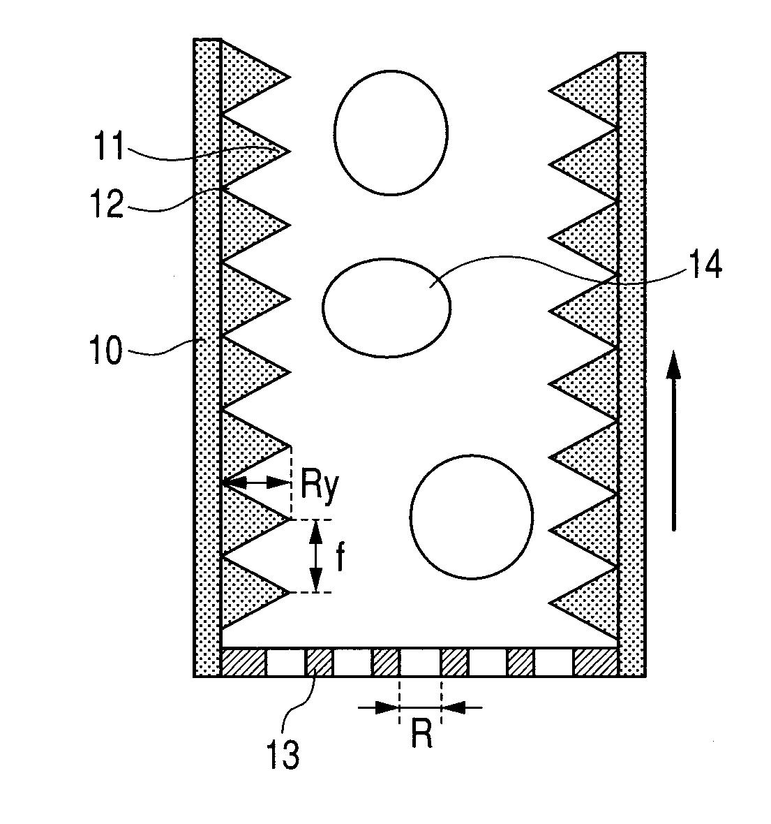
[0056]As an Example of the liquid supplying member 10 illustrated in FIG. 1, 48 kinds of trial products in which the combination of one period f (μm) of the spatial frequency of the inner wall surface shape and the maximum height Ry (μm) differs are manufactured and a depositing state of the bubbles to the inner wall surface is observed with respect to each trial product. With respect to any of the trial products, as a filter 13 illustrated in FIG. 1, the filter having the opening diameter of 15 (μm) is arranged inside of the edge portion. The combination conditions of one period f (μm) of the spatial frequency and the maximum height Ry (μm) in each trial product are as shown in the following Table 1. That is, with respect to one period f (μm) of the spatial frequency, it is made different every 5 (μm) within a range of 5 to 30 (μm). With respect to the maximum height Ry (μm), it is made different every 5 (μm) within a range of 5 to 40 (μm).

[0057]Any of the trial products is molded ...

example 2

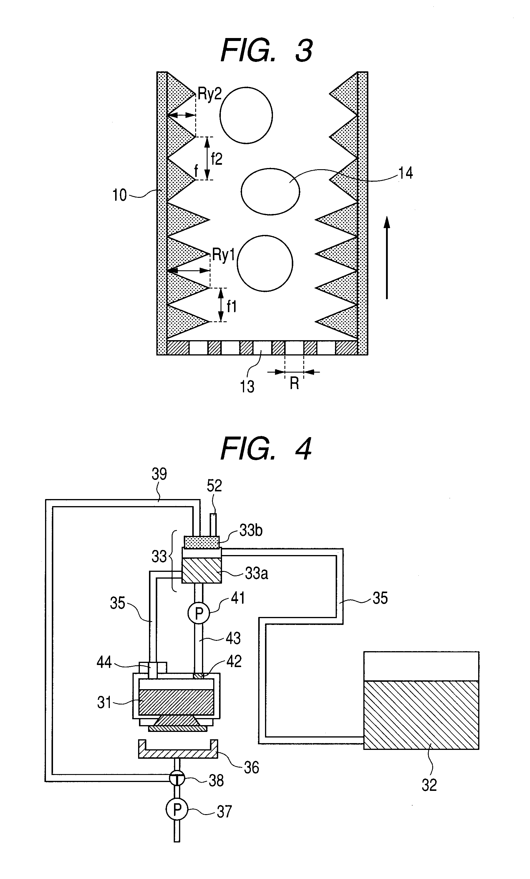
[0062]As an Example of the negative pressure unit 33 illustrated in FIG. 4, 48 kinds of trial products in which the combination of one period f (μm) of the spatial frequency and the maximum height Ry (μm) differs are manufactured and a depositing state of the bubbles to the inner wall surface is observed with respect to each trial product. The combination conditions of one period f (μm) of the spatial frequency and the maximum height Ry (μm) in each trial product are as shown in Table 1. Any of the trial products is molded by using the die.

[0063]Each trial product is built in the ink jet recording apparatus having the construction illustrated in FIG. 4. At this time, as a filter 42 illustrated in FIG. 4, the filter having an opening diameter of 15 (μm) is built in a recording head corresponding to the recording head 31.

[0064]In the ink jet recording apparatus in which each trial product has been built, the head recovery operation is executed and the collected ink containing the bubb...


PUM

PropertyMeasurementUnit
opening diameteraaaaaaaaaa
height Ryaaaaaaaaaa
height Ryaaaaaaaaaa

Abstract

A deposition of bubbles or foams to an inner wall of a liquid supplying member is prevented, thereby improving ejecting performance of the bubbles or foams. In the liquid supplying member which forms a flow path for supplying a liquid to a liquid discharging apparatus, the inner wall surface has a concave/convex shape in which a mountain portion and a valley portion are repeated at a predetermined spatial frequency. Assuming that an opening diameter of a filter provided for the liquid discharging apparatus is equal to R (μm), one period f (μm) of the spatial frequency lies within a range from R or more to √{square root over (2)}·R or less and a maximum height Ry (μm) of the mountain portion is equal to √{square root over (2)}·R/2 or more.

Description

BACKGROUND OF THE INVENTION[0001]1. Field of the Invention[0002]The present invention relates to a liquid supplying member, a negative pressure unit, and a liquid discharging apparatus.[0003]2. Description of the Related Art[0004]In a liquid discharging apparatus such as an ink jet recording apparatus, when bubbles are mixed into a liquid such as ink, the discharge becomes unstable or a discharge amount fluctuates. If bubbles exist in a tank for storing the ink, a flow path for supplying the ink stored in the tank to a liquid discharging head, or the like, the liquid is not smoothly supplied or circulated.[0005]In recent years, the ink jet recording apparatus is also used when an image or characters are recorded onto a sheet of a large size such as A1 format or A0 format.[0006]In the ink jet recording apparatus which consumes a large amount of ink as mentioned above, a main tank and the liquid discharging head (recording head) are connected through the negative pressure unit. The in...

Claims


Application Information

Patent Timeline
Patent Type & Authority Applications(United States)
IPC IPC(8): E03B7/07
CPCB41J2/19B41J2/17563Y10T137/794
Inventor AOYAMA, KAZUHIROSUEOKA, MANABUKURITA, YOSHIYUKI
Owner CANON KK
Why Eureka
Try Eureka