Piezoelectric inkjet printhead and method of manufacturing the same

a technology of inkjet printing and piezoelectric technology, applied in printing and other directions, can solve the problems of increasing the number of plate alignment processes, increasing the number of aligning errors, and inability to smoothly flow ink, so as to improve the ink ejection performance and simplify the manufacturing process

Inactive Publication Date: 2010-04-13
SAMSUNG ELECTRO MECHANICS CO LTD
View PDF6 Cites 6 Cited by
  • Summary
  • Abstract
  • Description
  • Claims
  • Application Information

AI Technical Summary

Benefits of technology

[0016]The present general inventive concept provides a piezoelectric inkjet printhead that is formed of two silicon substrates having identical nozzles to simplify a manufacturing process thereof and to improve an ink ejection performance thereof, and a method of manufacturing the piezoelectric inkjet printhead.

Problems solved by technology

However, since the conventional piezoelectric inkjet printhead is formed of a relatively large number of plates, the number of plate-aligning processes increases and thereby a number of aligning errors also increases.
In this case, ink cannot flow smoothly through an ink flow channel formed in the printhead, thereby deteriorating an ink ejecting performance of the printhead.
Further, precise aligning may influence a price of the printhead.
In addition, since the plates of the printhead are formed of different materials using different methods, the manufacturing process of the printhead is complicated and it is difficult to bond the plates, thereby decreasing a manufacturing yield of the printhead.
Further, since the plates of the printhead are formed of different materials, the alignment of the plates may be affected or the plates may be deformed according to a temperature change due to different thermal expansion characteristics of the plates, even though the plates are precisely aligned and bonded together in the manufacturing process.
However, the inkjet printhead manufactured using the three substrates 30, 40, and 50 has low driving frequency and high manufacturing costs.
Further, when a number of ink introducing portions 51b are formed by wet etching as described above, it is difficult to keep the ink introducing portions 51b at a constant depth such that a length of the ink introducing portions 51b may deviate from a desired value.

Method used


Image

  • Piezoelectric inkjet printhead and method of manufacturing the same
  • Piezoelectric inkjet printhead and method of manufacturing the same
  • Piezoelectric inkjet printhead and method of manufacturing the same

Examples


Embodiment Construction

[0057]Reference will now be made in detail to the embodiments of the present general inventive concept, examples of which are illustrated in the accompanying drawings, wherein like reference numerals refer to the like elements throughout. The embodiments are described below in order to explain the present general inventive concept by referring to the figures. The thicknesses of layers and regions are exaggerated for clarity. It will also be understood that when a layer is referred to as being “on” another layer or substrate, it can be directly on the other layer or substrate, or intervening layers may be present therebetween.

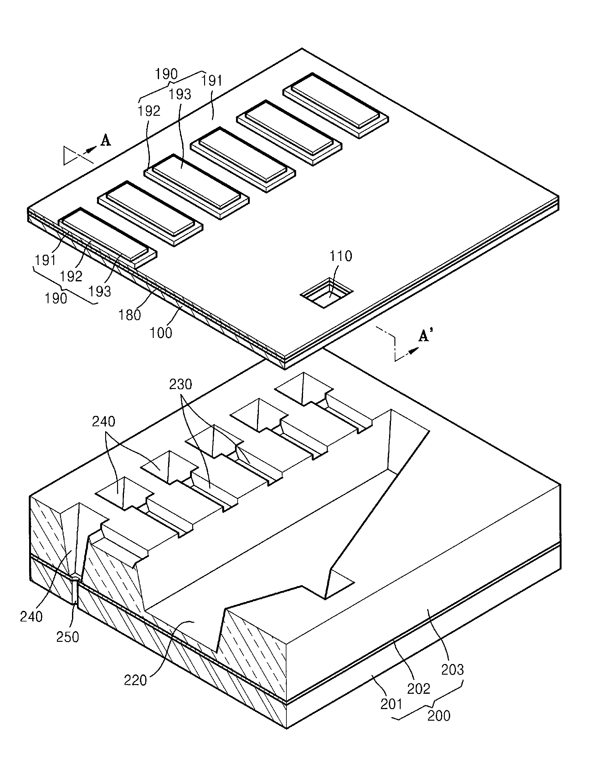
[0058]FIG. 3A is an exploded perspective view illustrating a part of a piezoelectric inkjet printhead according to an embodiment of the present general inventive concept, and FIG. 3B is a vertical section along line A-A′ of FIG. 3A.

[0059]Referring to FIGS. 3A and 3B, the piezoelectric inkjet printhead according to the present embodiment is formed by bonding two ...


PUM

PropertyMeasurementUnit
thicknessaaaaaaaaaa
thicknessaaaaaaaaaa
thicknessaaaaaaaaaa

Abstract

A piezoelectric inkjet printhead including an upper substrate formed of a single crystal silicon substrate or an SOI substrate and having an ink inlet therethrough, and a lower substrate formed of an SOI substrate having a sequentially stacked structure with a first silicon layer, an intervening oxide layer, and a second silicon layer in which a manifold, pressure chambers, and dampers are formed in the second silicon layer by wet or dry etching, and nozzles are formed through the intervening oxide layer and the first silicon layer by dry etching, and a method of manufacturing the same.

Description

CROSS-REFERENCE TO RELATED APPLICATIONS[0001]This application claims priority under 35 U.S.C. §119(a) from Korean Patent Application No. 10-2006-0008239, filed on Jan. 26, 2006, in the Korean Intellectual Property Office, the disclosure of which is incorporated herein in its entirety by reference.BACKGROUND OF THE INVENTION[0002]1. Field of the Invention[0003]The present general inventive concept relates to an inkjet printhead, and more particularly, to a piezoelectric inkjet printhead formed of two silicon substrates using a micro-fabrication technology and a method of manufacturing the piezoelectric inkjet printhead.[0004]2. Description of the Related Art[0005]Generally, inkjet printheads are devices for printing a color image on a printing medium by ejecting droplets of ink onto a desired region of the printing medium. Depending on the ink ejecting method, the inkjet printheads can be classified into two types: thermal inkjet printheads and piezoelectric inkjet printheads. The th...

Claims


Application Information

Patent Timeline
Patent Type & Authority Patents(United States)
IPC IPC(8): B41J2/045
CPCB41J2/14233B41J2/161B41J2/1623B41J2/1629B41J2/1628Y10T29/49401Y10T29/42B41J2/045
Inventor LEE, JAE-CHANGCHUNG, JAE-WOOLEE, KYO-YOOLLEE, CHANG-SEUNGKANG, SUNG-GYU
Owner SAMSUNG ELECTRO MECHANICS CO LTD
Why Eureka
Try Eureka