Heat dissipation device and lighting device

a heat dissipation device and heat dissipation technology, which is applied in the direction of semiconductor devices for light sources, lighting and heating apparatus, fixed installations, etc., can solve the problems of poor light emission efficiency, shorten the life of leds, and difficulty in obtaining the necessary amount of light, etc., to achieve efficient transfer, small size, and high degree of freedom of layout design

Inactive Publication Date: 2010-11-11
SHARP KK
View PDF7 Cites 43 Cited by
  • Summary
  • Abstract
  • Description
  • Claims
  • Application Information

AI Technical Summary

Benefits of technology

[0035]In the present invention, an LED is used as a light source, and the LED is small in size and has a high degree of freedom for layout design. Therefore, by appropriately mounting the LED on the heat dissipation device, for example, placing the LED according to the position of the inner tube, the heat generated by the LED is efficiently transferred to the inner tube and dissipated.
[0036]According to the present invention, the heat dissipation performance is improved without increasing the external dimensions.

Problems solved by technology

In particular, in a lighting device using a light emitting diode (hereinafter referred to as the LED) as a light source, a rise in the temperature of the LED may shorten the life of the LED and cause poor light emitting efficiency and a problem of difficulty in obtaining a necessary amount of light.
In particular, since a downlight is installed from the room side, the external dimensions are limited by the size of a mounting hole, and the height is also limited by the space above the ceiling.
However, when the number of fins is increased, the space between the fins, particularly the space between the bases of the fins becomes narrower, the air is hard to flow to the vicinity of the bases of the fins where temperature is higher, and consequently there is a possibility that sufficient heat transfer from the fins to air is not achieved.

Method used


Image

  • Heat dissipation device and lighting device
  • Heat dissipation device and lighting device
  • Heat dissipation device and lighting device

Examples


embodiment 1

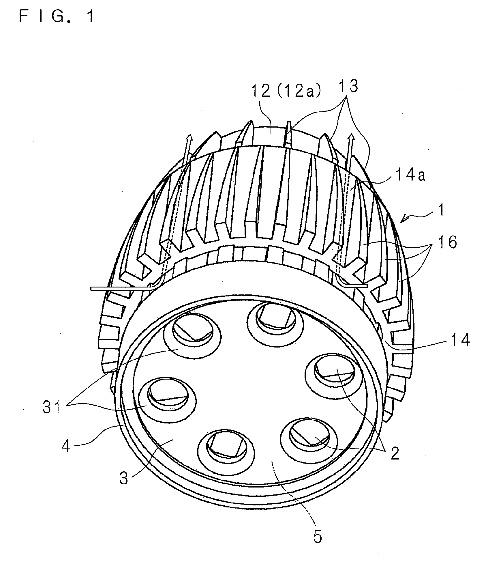
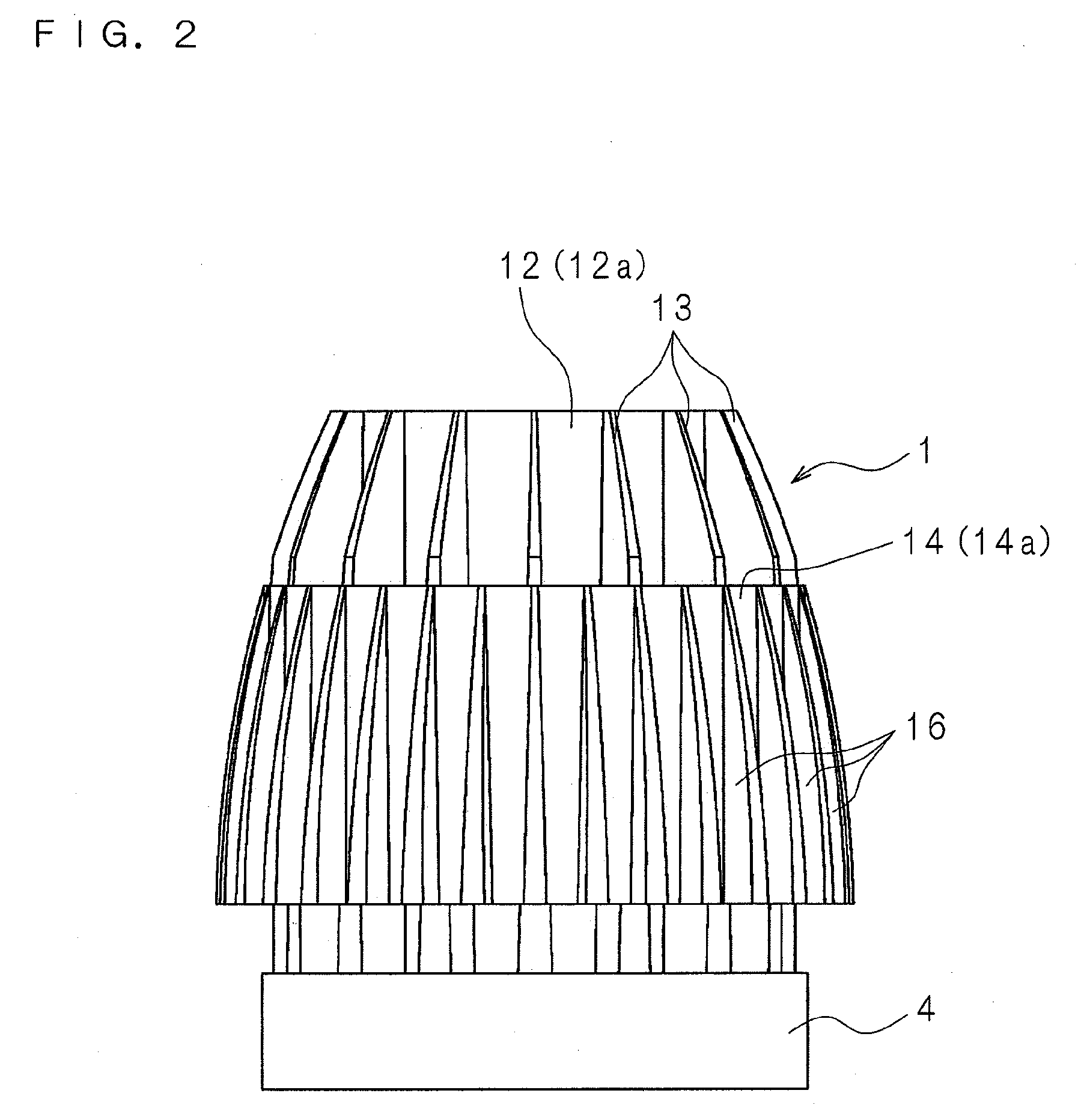
[0070]FIG. 1 is an external perspective view of a lighting device according to Embodiment 1 of the present invention. FIG. 2 is a schematic side view of the lighting device, and FIG. 3 is a schematic rear view of the lighting device. FIG. 4 is a schematic cross sectional view taken along the Iv-Iv line of FIG. 3.

[0071]Reference numeral 1 in FIG. 1 is a heat dissipation device made of a metal, such as aluminum. The heat dissipation device 1 has the shape of a cylinder with a reduced diameter on one side in the axial direction of the cylinder, or a so-called shell-like shape.

[0072]The heat dissipation device 1 has a heat transfer plate 11 in the form of a circular plate. On one surface 11a of the heat transfer plate 11, a cylindrical inner tube 12 is disposed upright concentrically with the heat transfer plate 11. The thickness of the inner tube 12 changes successively in the axial direction so that the inner tube 12 is thicker on the side adjacent to the heat transfer plate 11 and th...

embodiment 2

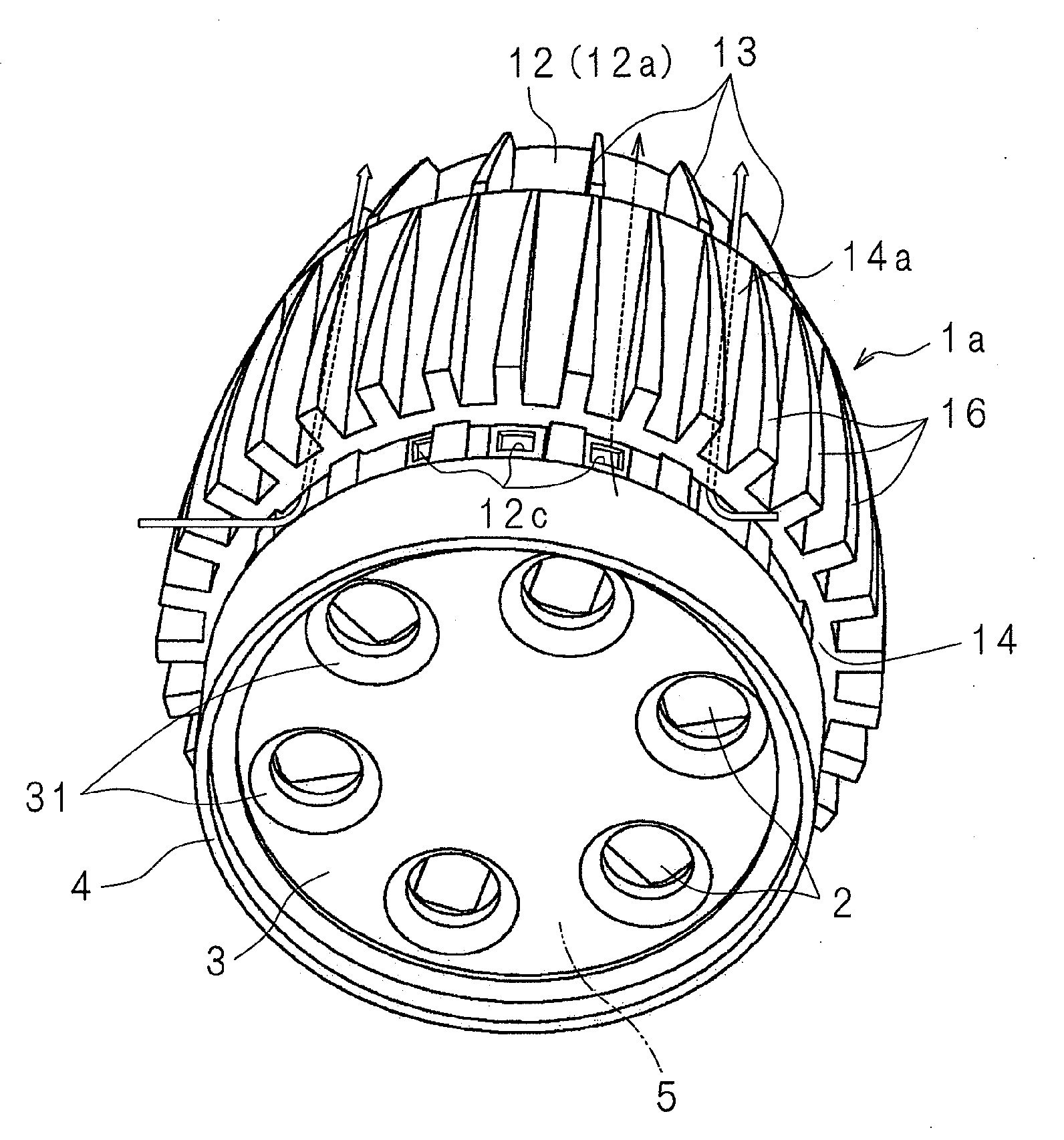
[0092]FIG. 5 is an external perspective view of a lighting device according to Embodiment 2 of the present invention. On an end of the inner tube 12 of a heat dissipation device 1a on a side where the LED modules 2, 2 are mounted, rectangular vents 12c, 12c . . . are provided at equal intervals in the circumferential direction between the first fins 13, 13 . . . . Since other structures are the same as those in Embodiment 1 illustrated in FIG. 1, the corresponding component members are designated with the same reference numerals as in FIG. 1 and detailed explanations of the structures will be omitted.

[0093]By configuring the heat dissipation device 1a in the above-described manner, heat generated in the LED modules 2, 2 . . . when the LED modules 2, 2 . . . are turned on is transferred to the inner tube 12, and the air in the inner tube 12 is warmed. The warmed air flows out from the open end of the inner tube 12 as indicated by the arrows in FIG. 5, while the outside air flows in f...

embodiment 3

[0094]FIG. 6 is a schematic partial cross sectional view of a lighting device according to Embodiment 3. On the circumferential edge of one surface 11a of the heat transfer plate 11 of a heat dissipation device 1b, a turbulence promoter 11d is formed in a protruding manner over the entire circumference to face the inner tube 12. The height H of the turbulence promoter 11d is preferably determined so that the relationship with distance L between the turbulence promoter 11d and the inner tube 12 satisfies a predetermined condition (L≈10H). Since other structures are the same as those in Embodiment 1 illustrated in FIG. 4, the corresponding component members are designated with the same reference numerals as in FIG. 4, and detailed explanations of the structures will be omitted.

[0095]By configuring the heat dissipation device 1b in the above-described manner, the flow of air entering the ventilation paths 15, 15 . . . is disturbed by the turbulence promoter 11d and produces eddies, and...


PUM

PropertyMeasurementUnit
distanceaaaaaaaaaa
total reflectanceaaaaaaaaaa

Abstract

A heat dissipation device according to the present invention includes an inner tube to which heat from LED modules is to be transferred, first fins protruding from an outer surface of the inner tube in a direction crossing the outer surface, and an outer tube covering the inner tube. Moreover, heat is transferred from the surfaces of the inner tube, outer tube and first fins which form ventilation paths (medium paths) to the air flowing at an increased flow rate by a stack effect.

Description

[0001]This application is the national phase under 35 U.S.C. §371 of PCT International Application No. PCT / JP2008 / 72147 which has an International filing date of Dec. 5, 2008 and designated the United States of America.BACKGROUND[0002]1. Technical Field[0003]The present invention relates to a heat dissipation device for dissipating heat from a heat generating element to the outside by natural convection, and also relates to a lighting device having the heat dissipation device.[0004]2. Description of Related Art[0005]In general, a lighting device contains therein heat generating components (heat generating elements) such as a light source and power source circuit components. Therefore, the lighting device needs to be configured so that a rise in the temperatures of the heat generating elements stored inside is reduced to ensure the performance of the heat generating components and a rise in the outside temperature of the lighting device is also reduced from the safety point of view. ...

Claims


Application Information

Patent Timeline
Patent Type & Authority Applications(United States)
IPC IPC(8): F28F13/12F28F1/20F28F13/18
CPCF21S8/02F21S8/026F21V29/004F21Y2101/02F21V29/83F21V29/75F21V29/763F21V29/773F21V29/78F21V29/74F21Y2115/10
Inventor YAMAMOTO, HIROYUKIBANDO, OSAMUOKAMURA, NORITAKA
Owner SHARP KK
Why Eureka
Try Eureka