Magnetising assembly
a technology of magnetisers and assemblies, applied in the field of magnetisers, can solve the problems of increasing flux in the circuit, and achieve the effects of reducing the effect of flux leakage, reducing the effect of function, and preventing or minimising flux leakag
- Summary
- Abstract
- Description
- Claims
- Application Information
AI Technical Summary
Benefits of technology
Problems solved by technology
Method used
Image
Examples
first embodiment
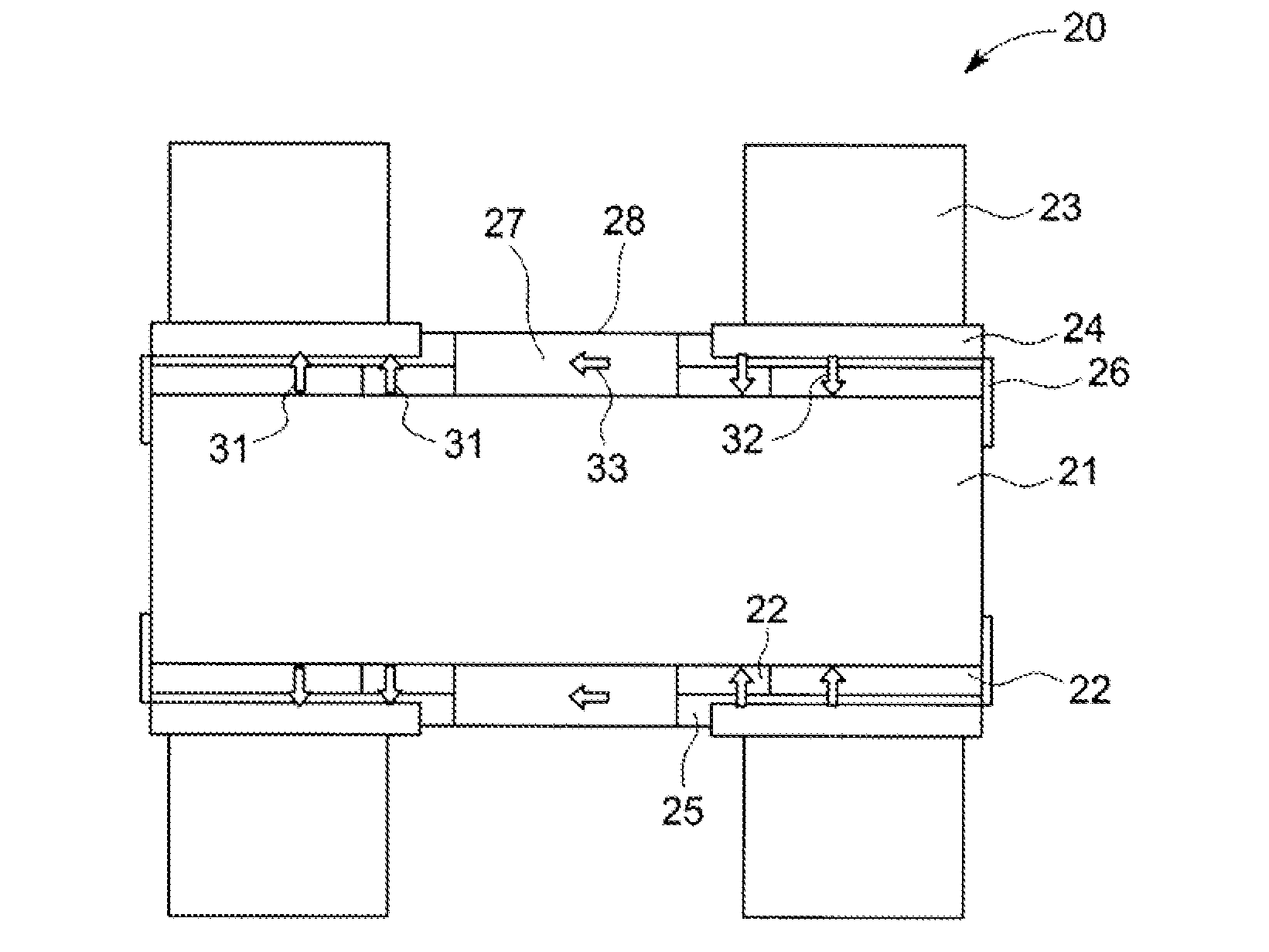
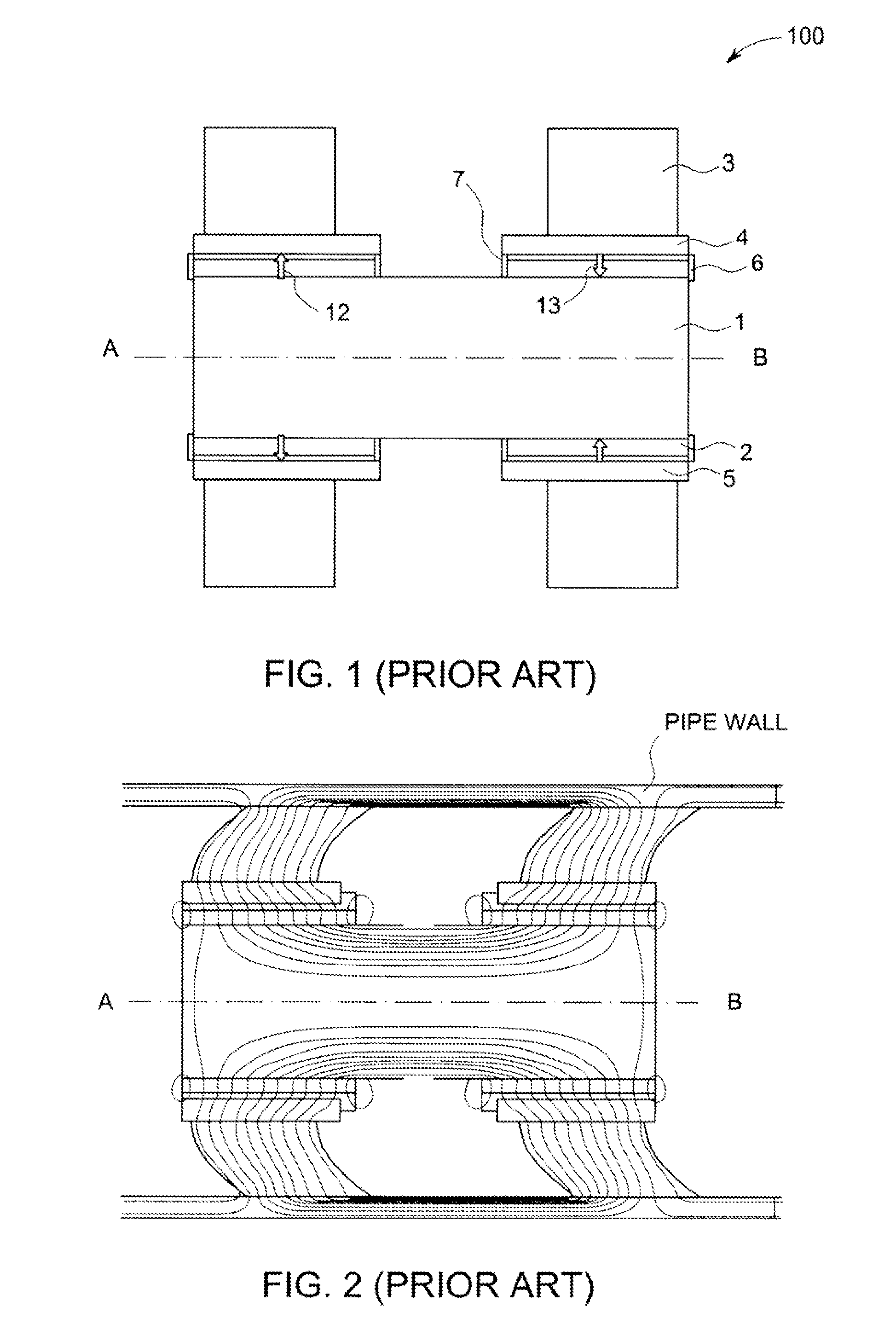
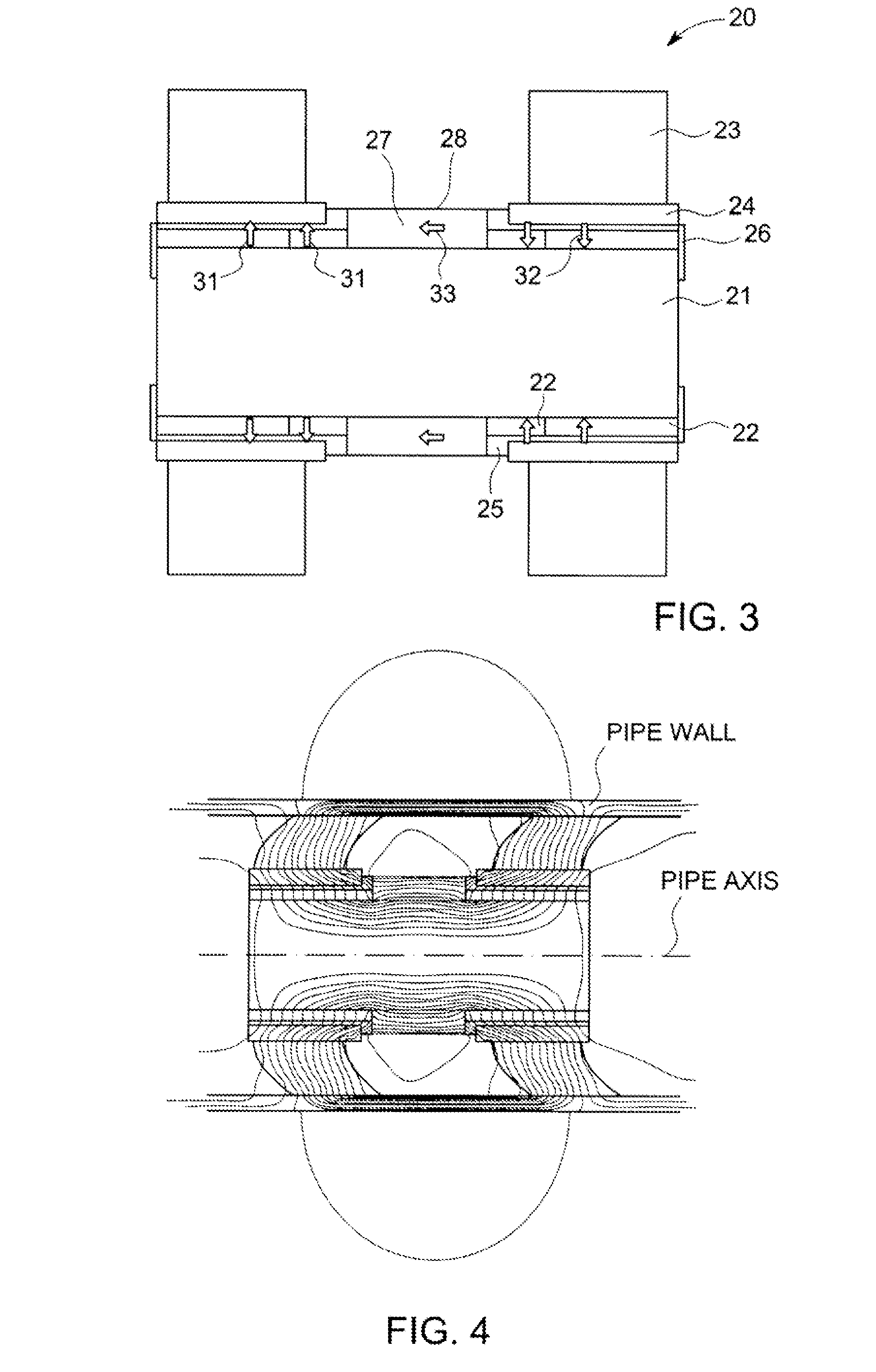
[0051]FIG. 4 shows a contour plot of lines of magnetic potential for the first embodiment inside a pipe. When compared with the plot shown in FIG. 2, it may be seen that the presence of the flux enhancing magnet acts to supplement and push the flux through the adjacent steel components.
[0052]The magnetic potential plot shown in FIG. 4 serves to show the flux lines or distribution of magnetic potential. FIG. 5 illustrates quantitatively the superiority of the invention. FIG. 5 is a graphical representation of the axial component of field in the pipe wall for a conventional magnetiser without a flux enhancing magnet (dotted line) and a magnetiser with a flux enhancing magnet according to the invention (solid line). The vertical axis represents field magnitude (in arbitrary units) and the horizontal axis represents the distance along the pipe. A peak in the field magnitude occurs between the flux couplers, where MFL sensors may be located. FIG. 5 shows that in the peak region, the fiel...
second embodiment
[0054]FIG. 6 is cross-section view through a central body-type magnetiser 40 that is the invention. Components in FIG. 6 which perform the same function as those in FIG. 3 are given the same reference numbers. In this embodiment, the central body 21 tapers, i.e. exhibits a conical shape, underneath the driving magnets 22. The driving magnets 22 (specifically the main part of each driving magnet) are fitted to the tapered body. As a result, the radial thickness of the driving magnets increase towards their respective end plates 26. The purpose of this thickening is to increase the magneto-motive force of the assembly in this region and contribute to an additional increase in the pipe wall field.
third embodiment
[0055]FIG. 7 is cross-section view through a central body-type magnetiser 42 that is the invention. Components in FIG. 7 which perform the same function as those in FIG. 3 are given the same reference numbers. In this embodiment, the flux enhancing magnet 37 includes a recess 38 formed in its outer surface. In other words, the outer diameter of the flux enhancing magnet 37 is reduced over its central section. The purpose of this thinning may be to accommodate sensors and / or other inspection electronics on the tool. FEM may be used to find a configuration where the recess is of a suitable size for receiving sensors or the like yet the flux enhancing magnet still confers an adequate increase in field strength.
PUM
| Property | Measurement | Unit |
|---|---|---|
| magnetisation | aaaaa | aaaaa |
| magnetic flux | aaaaa | aaaaa |
| magnetic field | aaaaa | aaaaa |
Abstract
Description
Claims
Application Information
 - R&D
- Intellectual Property
- Life Sciences
- Materials
- Tech Scout
- Unparalleled Data Quality
- Higher Quality Content
- 60% Fewer Hallucinations
Browse by: Latest US Patents, China's latest patents, Technical Efficacy Thesaurus, Application Domain, Technology Topic, Popular Technical Reports.
© 2025 PatSnap. All rights reserved.Legal|Privacy policy|Modern Slavery Act Transparency Statement|Sitemap|About US| Contact US: help@patsnap.com


