
Method for surveillance to detect a land target

a technology for detecting land targets and surveillance, applied in the direction of measuring devices, using reradiation, instruments, etc., can solve the problems of difficulty, rvs cameras do not automatically detect movement, and cannot automatically detect movemen

Inactive Publication Date: 2010-11-11
VISTA RES INC
View PDF29 Cites 33 Cited by
  • Summary
  • Abstract
  • Description
  • Claims
  • Application Information

AI Technical Summary

Benefits of technology

The system achieves high probability of detection and low false alarm rates, allowing for effective border security by automatically detecting and tracking targets, reducing operator workload, and enabling timely apprehension of illegal crossings.

Problems solved by technology

The inadequacy of the current surveillance sensor algorithm and automatic false alarm mitigation technology, the excessively large number of illegal aliens attempting to cross the border, and the lack of sufficient agents to verify possible crossings and to apprehend the illegal aliens makes this a very difficult problem.
The report further states that the existing RVS cameras do not automatically steer and cover the area where a seismic or magnetic sensor alarm occurs and do not have the ability to detect movement automatically without operator input.
Thus, with existing systems being used at the U.S. borders, it is possible for illegal activity to go unnoticed if an agent is not manning the video terminals or misses some activity on the screen.
While the ice and snow can impair visual acuity along the Northern Borders, the hot and humid conditions can impact the performance of the RVS cameras and the resolution of the IR systems.
The poor performance of the present technology-based systems is due partially to the lack of integration between the sensors and the RVS cameras, the high number of false alarms of the sensors, and the lack of automation for the present camera systems.
The 24 / 7 requirement for visual inspection of the camera images by an operator, and the requirement to deal with a sensor alert every 44 s is too people-intensive to work over an extended period of time.
Detection of small cross-section targets such as people or groups of people that can potentially cross a border, especially one that is large, is a challenging technical problem if it is to be accomplished in a cost effective method.
The problem is made even more difficult when the measurements need to be made at ranges up 10 km or more for detection, tracking, and classification.
People, with very cross sections (less than 1 m2) are very difficult to detect.
However, as described below, this approach has experienced problems with an unacceptably high false alarm rate and a poorer than desired probability of detection.
The former results in an expensive misuse of limited resources, and the later does not provide the desired border security.
However, these radars are very expensive and to realize acceptable coverage for border surveillance applications would generally not be cost effective.
The less expensive non-coherent radars have not been used for border surveillance applications because of the lack of capability to detect very small cross-section targets like people.
Finally, our search did not indicate the use of a radar propagation model for locating towers or mobile vehicle for optimal coverage, or for use in developing more robust tracks of the targets of interest.

Method used


Image

  • Method for surveillance to detect a land target
  • Method for surveillance to detect a land target
  • Method for surveillance to detect a land target

Examples


Embodiment Construction

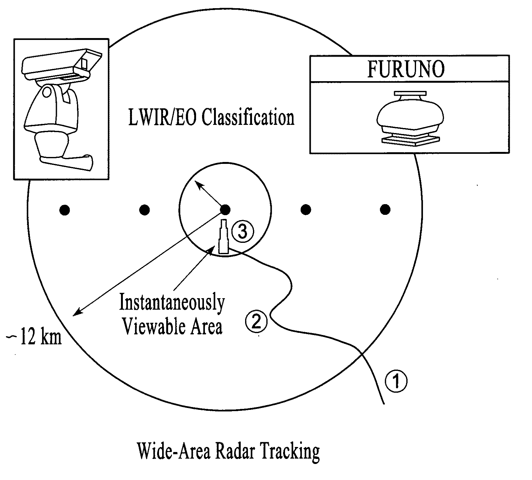
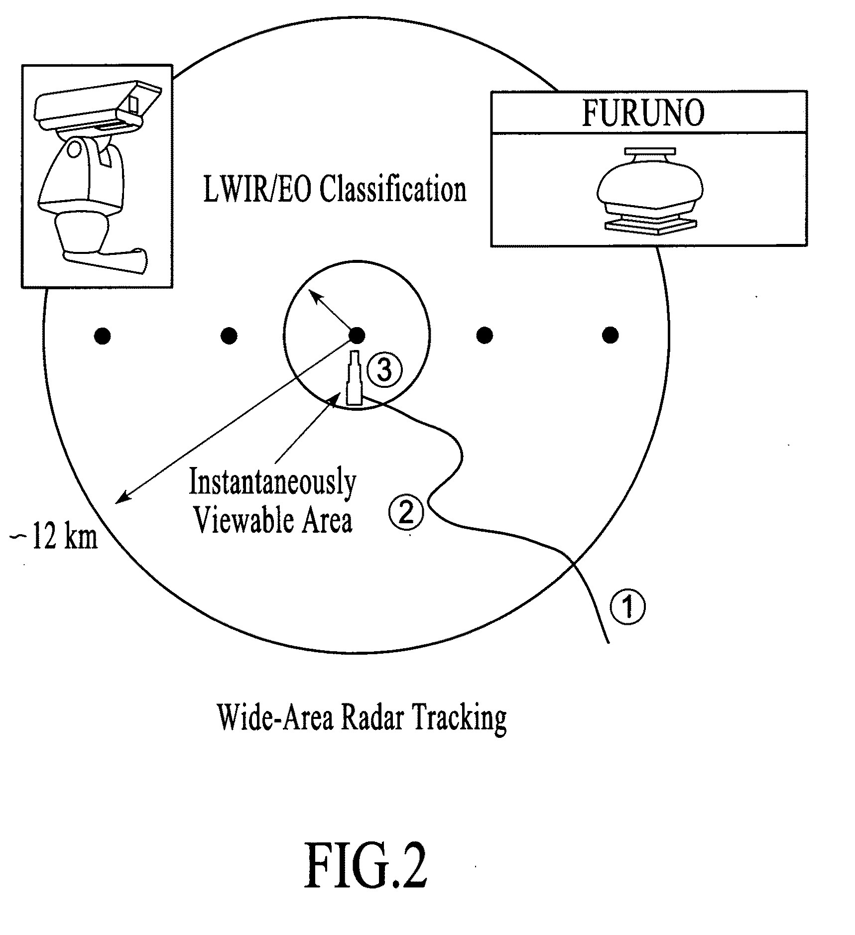
[0081]FIGS. 2 and 3 illustrate schematically the preferred embodiment of a Smart-Sensor System in a tower-based system architecture. The same preferred embodiment could be used in a mobile vehicle with a mast or any other type of structure that allows the embodiment to be elevated sufficient to see the targets in the target area of interest. The primary components of the preferred embodiment of the Smart-Sensor System are (1) a low-cost, COTs, non-coherent radar, whose objective is to detect and track all targets of interest (TOI) out to ranges of 12 km and to cue (2) a narrow field-of-view FOV), long-wave infrared (LWIR) sensor, whose objective is to classify the cued target out to ranges of up to 6 km, and (3) a supercomputer to process the data in real-time at the base of the tower.

[0082]It is important to point out that the essential element of the radar is that a non-coherent radar is used. The preferred embodiment uses a K-band radar, but other frequencies of operation (C-band...


PUM


Abstract

A land-based Smart-Sensor System and several system architectures for detection, tracking, and classification of people and vehicles automatically and in real time for border, property, and facility security surveillance is described. The preferred embodiment of the proposed Smart-Sensor System is comprised of (1) a low-cost, non-coherent radar, whose function is to detect and track people, singly or in groups, and various means of transportation, which may include vehicles, animals, or aircraft, singly or in groups, and cue (2) an optical sensor such as a long-wave infrared (LWIR) sensor, whose function is to classify the identified targets and produce movie clips for operator validation and use, and (3) an IBM CELL supercomputer to process the collected data in real-time. The Smart Sensor System can be implemented in a tower-based or a mobile-based, or combination system architecture. The radar can also be operated as a stand-alone system.

Description

[0001]This application claims the benefit of U.S. Provisional Patent Application Ser. No. 60 / 804,251 filed Jun. 8, 2006.BACKGROUND OF THE INVENTION[0002]1. Field of the Invention[0003]The method and apparatus described herein are motivated by the need for surveillance and security of the land borders of the United States, including property and facility borders such as military bases and nuclear / petroleum facilities, respectively. The border surveillance system will detect, track, and / or classify people or vehicles automatically and in real-time that are approaching, that may attempt to cross, or have crossed a border. The surveillance method is comprised of (1) a radar for wide-area surveillance to detect, track, and perform 1st stage classification of potential targets that cues (2) one or more optical sensors, which may be comprised of one or more infrared (IR) and electro-optical (EO) sensor systems, and / or coherent radars, for classification of these targets, and (3) a supercom...

Claims


Application Information

Patent Timeline
Patent Type & Authority Applications(United States)
IPC IPC(8): G01S13/00
CPCG01S7/2922G01S13/522G01S13/867G01S13/86G01S13/886G01S13/723
Inventor FOX, PHILLILP A.MARESCA, JR., JOSEPH W.
Owner VISTA RES INC
Learn More