
Thermal management system for computers

a technology of management system and computer, applied in the direction of electrical apparatus construction details, electrical apparatus casing/cabinet/drawer, instruments, etc., can solve the problems of soft failure, memory module density, affecting the functionality of high-performance computing systems, etc., and achieve the effect of more efficient use of spa

Inactive Publication Date: 2008-08-14
MICROELECTRONICS ASSEMBLY TECH
View PDF17 Cites 34 Cited by
  • Summary
  • Abstract
  • Description
  • Claims
  • Application Information

AI Technical Summary

Problems solved by technology

Heat generation from semiconductor devices impedes functionality in high performance computing systems such as the blade server market sector.
An increase in memory modules density is accompanied by significant heat generation, which leads to soft failures (Corrupt data stream).
This is unacceptable to medical, financial & military centers.
Second, forced air is used to carry the heat away from devices and out of the blade server enclosure.
The heat sinks are so thick that they obstruct the air channels between adjacent modules.

Method used


Image

  • Thermal management system for computers
  • Thermal management system for computers
  • Thermal management system for computers

Examples


example 1.2

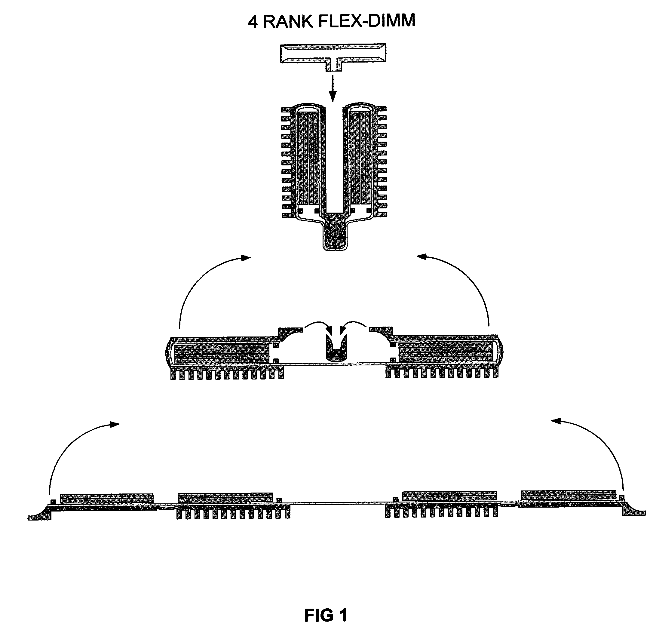
RANK FLEX DIMM

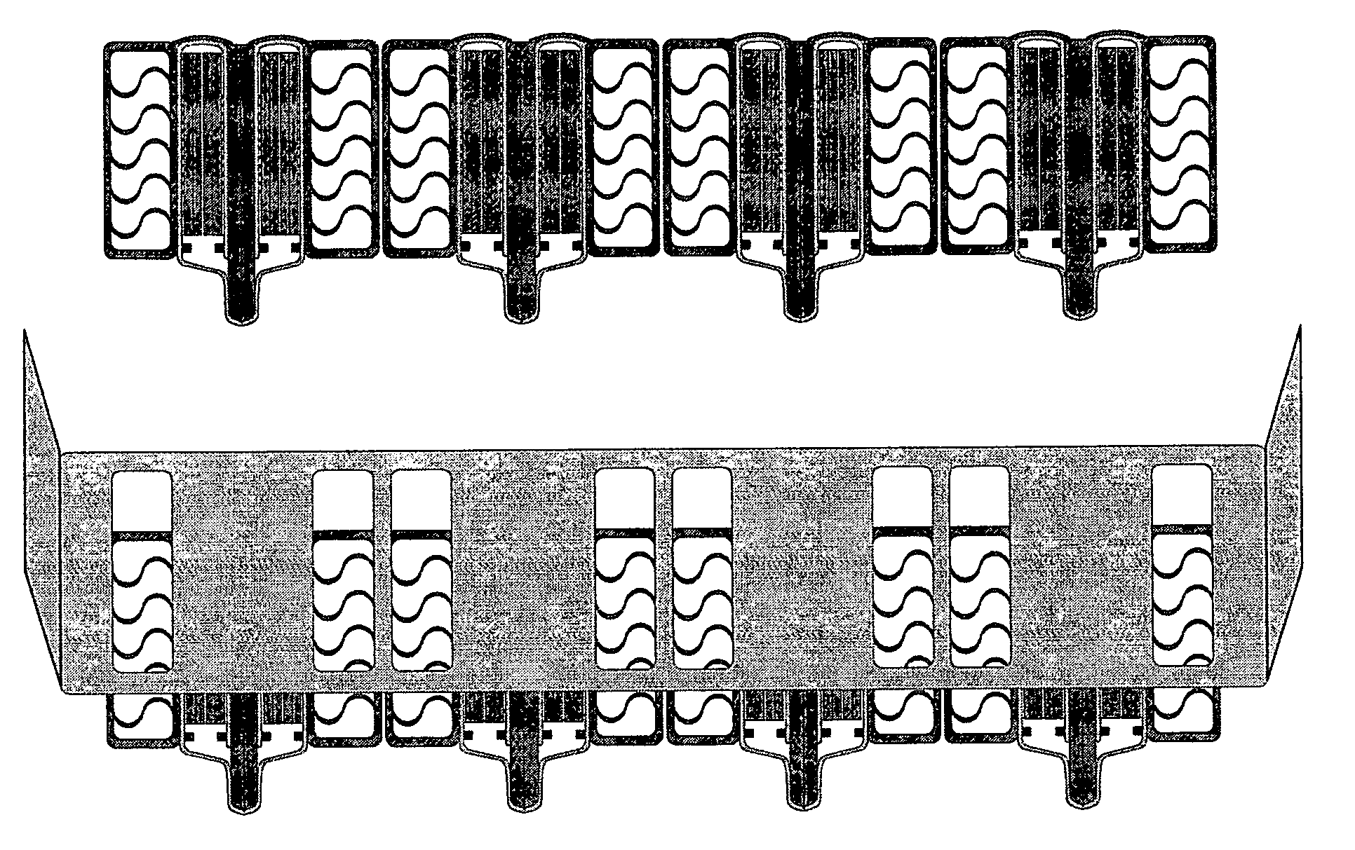
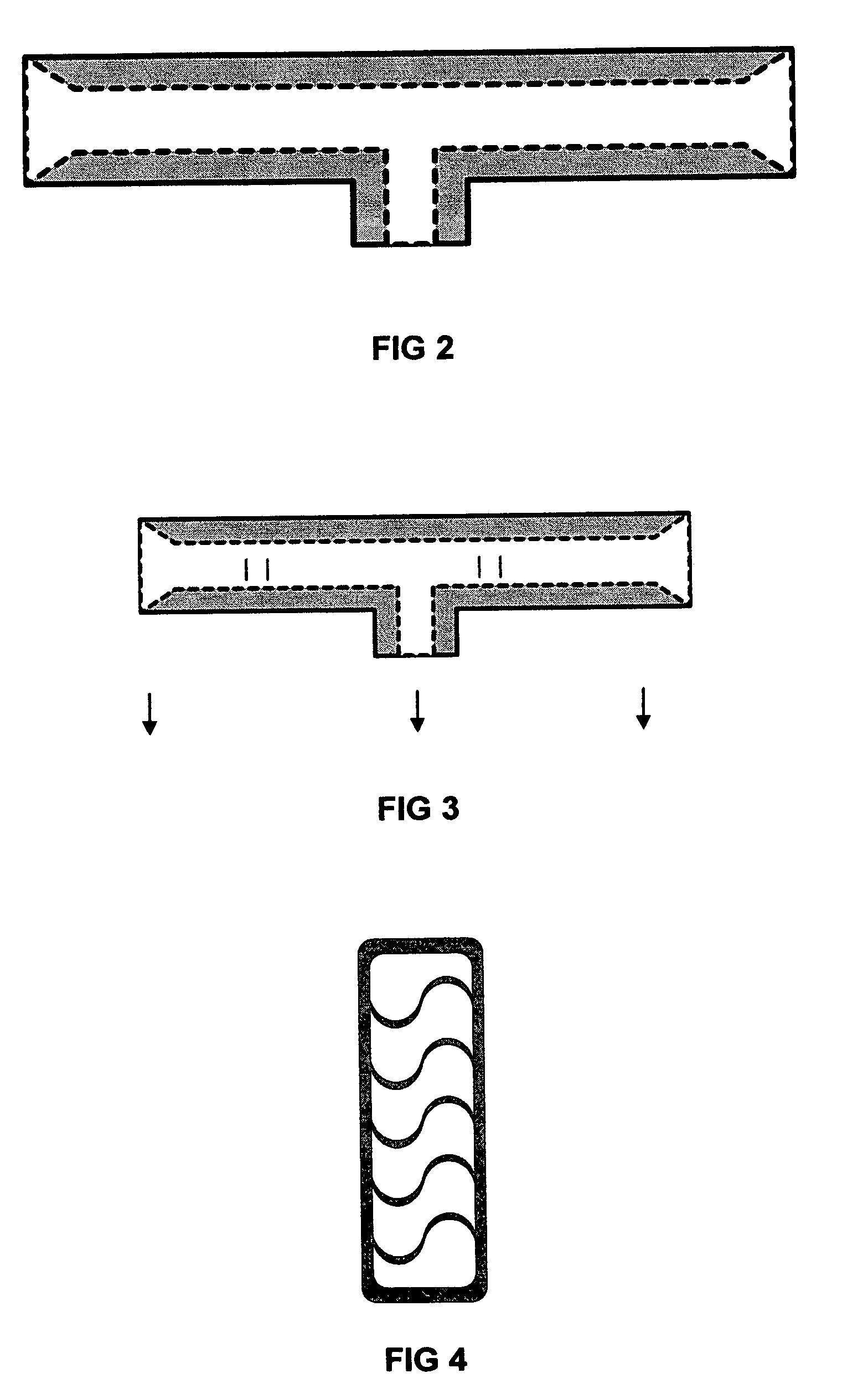
[0031]The single sided cooling Flex DIMM module consists of semiconductor components mounted to and interconnected by a multilayer flex circuit that is integrally (and thermally) coupled to the base side of a single sided heat sink. This configuration is mirrored about the center plane of the module completing the assembly. The removal of heat from the semiconductor devices is accomplished by conducting heat away from the component, through the flex circuit, and directly into the cooling air stream by the means of a single sided high performance forced convection heat sink. This heat sink utilizes a forced air convection heat transfer process to transport the heat from the heat sink base out to the dissipating surfaces and then into the cooling air stream. The forced convection cooling air stream impinges onto one end of the Flex DIMM module heat sink, and flows along the length of the heat sink dissipating surface. The high performance forced convection heat sink acco...

example 2.4

RANK FLEX DIMM

[0032]The double sided cooling Flex DIMM module consists of semiconductor components mounted to and interconnected by a multilayer flex circuit that is integrally coupled to both sides of a double sided cold plate heat exchanger. This configuration is mirrored about the center plane of the module completing the assembly. The removal of heat from the semiconductor devices is accomplished by conducting heat away from the component, through the flex circuit, and directly into the cooling air stream by the means of a double sided, high performance, forced convection, cold plate heat exchanger. This heat exchanger utilizes a forced air convection heat transfer process to transport the heat from the heat exchanger sidewalls, to the dissipating surfaces, and into the cooling air stream. The forced convection cooling air stream impinges onto one end of the Flex DIMM module heat exchanger, and flows through the length of the enclosed heat exchanger sidewalls, across the heat ex...


PUM


Abstract

The invention involves systems to channel the air available for cooling inside the chassis of the computing device to force the air into selected channels in the memory bank (i.e., between the modules rather than around the modules or some other path of least resistance). This tunneled cooling (or collimated cooling) is made possible by using a set of baffles (or apertures) placed upstream of and between the cooling air supply and the memory bank area to force air to go only through the rectangular space available between adjacent modules in the memory bank of the high speed computing machines (super computers or blade servers in these cases). In some instances, it may be desirable to include both a blower fan, for forcing cool air through the baffles and through the heat exchanger(s) aligned with openings in the baffles, and a suction fan to draw or pull air as it exits the rear of the blade server chassis. The invention includes a high performance heat exchanger to be thermally coupled to the memory chips and either placed between adjacent modules (in the memory bank) or integrated within a cross sectional area of the module that is in the cooling air path; whereby, the heat from a given module is transferred laterally to a heat sink that, in turn, transfers the heat to the heat exchanger which in turn is placed in the path of cool air. However in this case, the cool air has no other alternative path but to pass through the high performance heat exchanger. The efficiency of heat exhaust is thereby maximized. Lateral heat conduction and removal is a preferred method for module cooling in order to minimize the total module height of vertically mounted Very Low Profile (VLP) memory modules. The invention is applicable to a wide range of modules; however, it is particularly suitable for a set of memory modules with unique packaging techniques that further enhance the heat exhaust.

Description

CROSS REFERENCE TO RELATED APPLICATION[0001]This application claims the benefit of Provisional Patent Application No. 60 / 900,238 by the present inventors, filed on Feb. 8, 2007, the entire disclosure of which is incorporated herein by reference.BACKGROUND OF THE INVENTION[0002]1. Field of the Invention[0003]The invention pertains to systems and methods for managing heat generated in computers, and more particularly to systems and methods for managing coolant flow adjacent to various heat-generating components[0004]2. Description of Related Art[0005]Heat generation from semiconductor devices impedes functionality in high performance computing systems such as the blade server market sector. High-speed computers or Blade servers are space-constrained and their performance depends on the number of microprocessors and memory modules they contain. An increase in memory modules density is accompanied by significant heat generation, which leads to soft failures (Corrupt data stream). This i...

Claims


Application Information

Patent Timeline
Patent Type & Authority Applications(United States)
IPC IPC(8): G06F1/20H05K7/20
CPCG06F1/20H05K1/0203H05K1/189H05K3/0061H05K2201/10159H05K2201/056H05K2201/064H05K2201/09445H05K7/20727
Inventor CLAYTON, JAMES E.FATHI, ZAKARYAEGENTRY, JAMES R.
Owner MICROELECTRONICS ASSEMBLY TECH
Learn More