Moving image holography reproducing device and color moving image holography reproducing device

a holographic reproducing device and moving image technology, applied in the field of color moving image holographic reproducing device, can solve the problems of incomplete three-dimensional image, holography, and inability to re-create,

Inactive Publication Date: 2005-02-24
JAPAN SCI & TECH CORP
View PDF10 Cites 31 Cited by
  • Summary
  • Abstract
  • Description
  • Claims
  • Application Information

AI Technical Summary

Benefits of technology

[0032] In contrast, a liquid crystal display (LCD) is commonly used as an electronically controlled display device. Systems that use LCDs do not have the above-described drawbacks. The systems are capable of 1) reconstructing a complete three-dimensional image and 2) being completely electronically controlled. In addition, the LCD can be used simply by being connected to a computer. Accordingly, the LCD provides easy handling and, therefore, the LCD is a suitable device for CGH.
[0035] Compared to transmissive LCDs, reflective LCDs have two main advantages for reconstruction of a holographic image.
[0036] First, a reflective LCD structurally facilitates high pixel resolution. Since a reflective LCD has a control circuit on its back surface, liquid crystal elements can be closely arranged on a front surface of the reflective LCD.
[0037] Additionally, the structural advantage provides another advantage for the usability of light. That is, in a transmissive LCD, since a control circuit must be mounted on the same plane as liquid crystal elements, achieving a high aperture ratio is difficult. Consequently, the transmittance ratio is about 30% and, therefore, the reconstructed image is dark. In contrast, a reflective LCD can increase the reflectance ratio (theoretically greater than 90% is possible) and, therefore, a bright reconstructed image can be easily achieved. This is a second advantage.
[0042] Accordingly, it is an object of the present invention to provide a simple color moving-image holographic reproducing device that can reconstruct a high-resolution image by using a reflective liquid crystal display and further using a light-emitting diode as a reproducing light source.
[0043] It is another object of the present invention to provide a significantly simplified color moving-image holographic reproducing device that can achieve color holography by using a single-plate hologram without the need for time-multiplexing.

Problems solved by technology

(1) First, since the system eliminates vertical parallax, a complete three-dimensional image, which is the characteristic of holography, cannot be reconstructed.
This is not a problem for entertainment use because human perception of three-dimensions is more sensitive in the horizontal direction than in the vertical direction; however, this becomes a disadvantage in visualization of a numerical simulation, where the entire visualized structure is critical.
(2) Second, since the system uses a mechanical control unit, such as a polygon mirror, the entire system becomes complicated.
Compared to electronic control, mechanical control is inferior in terms of speed, physical dimensions, and reliability.
This is a big drawback for practical applications in the future.

Method used


Image

  • Moving image holography reproducing device and color moving image holography reproducing device
  • Moving image holography reproducing device and color moving image holography reproducing device
  • Moving image holography reproducing device and color moving image holography reproducing device

Examples


first embodiment

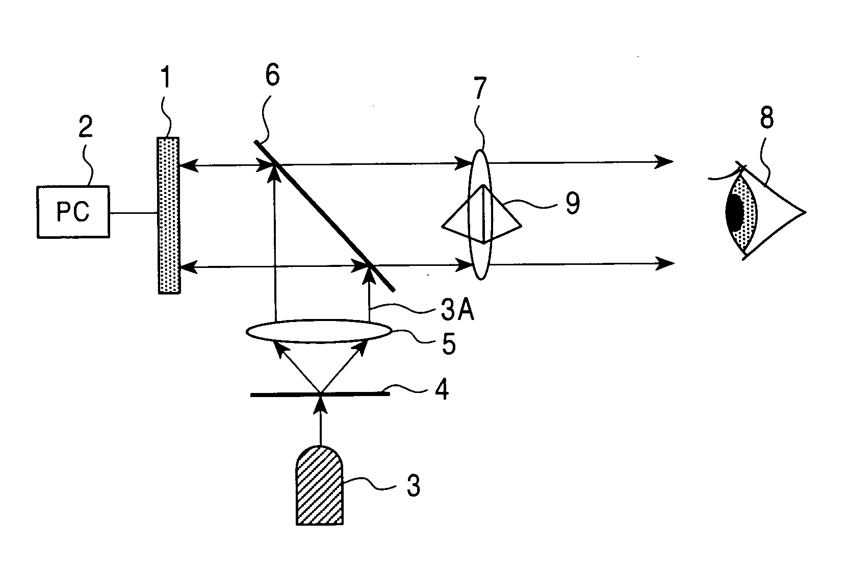
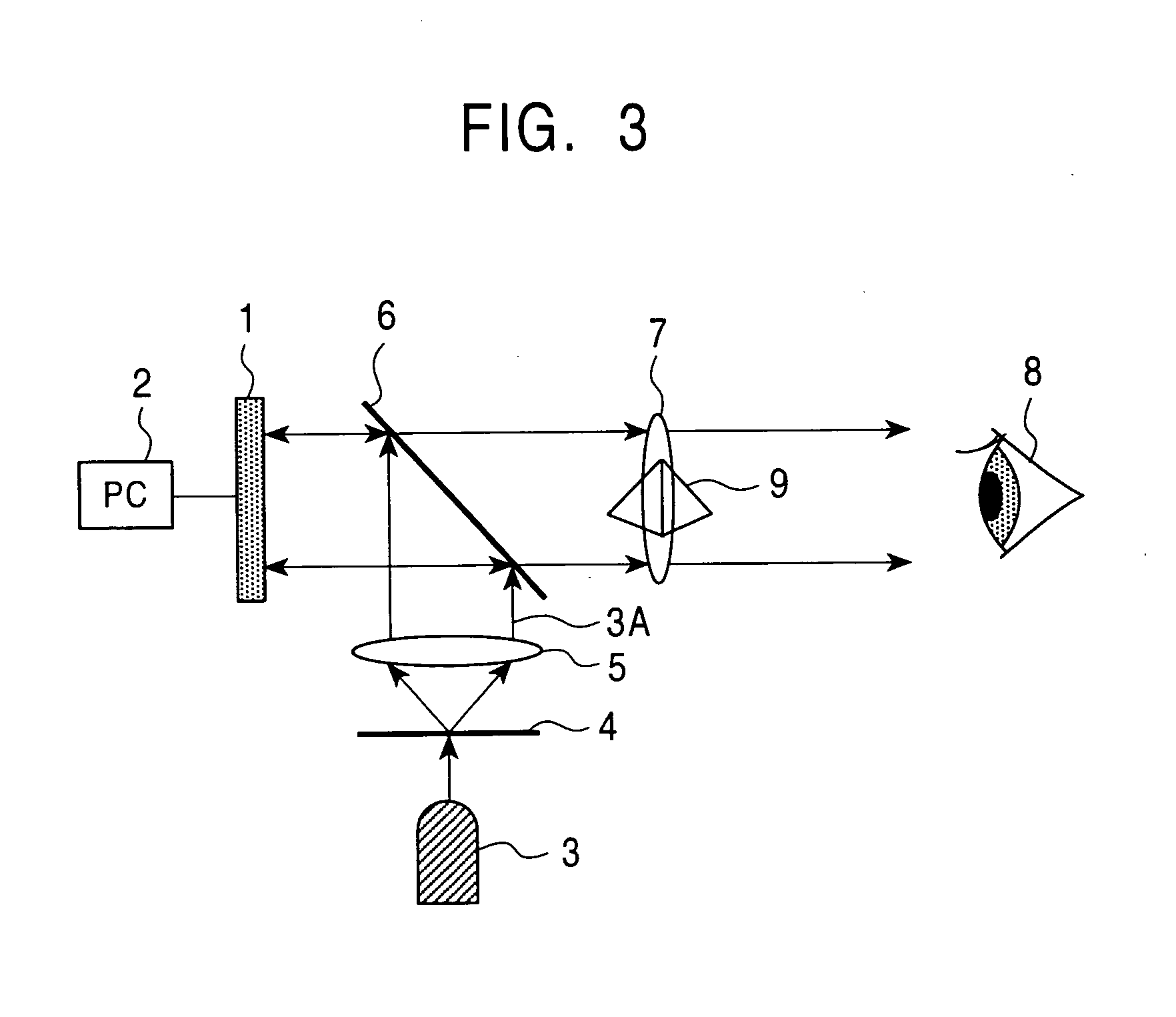
[0074]FIG. 3 is a block diagram of a moving-image holographic reproducing device including a reflective liquid crystal display and a light-emitting diode according to the present invention.

[0075] In the drawing, reference numeral 1 denotes a reflective liquid crystal display (reflective LCD). Reference numeral 2 denotes a personal computer (PC). Reference numeral 3 denotes a light-emitting diode (LED). Reference numeral 3A denotes LED light. Reference numeral 4 denotes a pinhole filter. Reference numeral 5 denotes a collimator lens. Reference numeral 6 denotes a beam splitter (half mirror). Reference numeral 7 denotes a field lens. Reference numeral 8 denotes an observer. Reference numeral 9 denotes a reconstructed image.

[0076] As can be seen, this moving-image holographic reproducing device is very simple. In this device, the reflective LCD 1 is, for example, the CMD8×6D available from Colorado MicroDisplay Inc. The CMD8×6D includes a small panel having a pixel pitch of 12 μm, 480...


PUM


Abstract

A moving-image holographic reproducing device that includes a reflective liquid crystal display and further a light-emitting diode functioning as a light source and that is capable of reproducing a high-resolution image in a simple way is provided. Also, a color moving-image holographic reproducing device that is capable of reproducing a color holographic image by a significantly simplified structure using a single plate hologram without the need for time-multiplexing is provided. The moving-image holographic reproducing device includes a computer for creating a hologram from three-dimensional coordinate data, a reflective liquid crystal display for displaying the hologram, a half mirror for projecting the displayed hologram, and a light-emitting diode, wherein a reconstructed three-dimensional image is displayed by illuminating the half mirror with light emitted from the light-emitting diode. Manipulating a sufficiently large size three-dimensional holographic image in real time requires computational power one thousand to ten thousand times higher than that of current supercomputers. According to the present invention, such an amount of information can be processed at high speed by dedicated hardware in a highly parallel and distributed manner.

Description

TECHNICAL FIELD [0001] The present invention generally relates to a moving-image holographic reproducing device and a color moving-image holographic reproducing device. More particularly, the present invention relates to a moving-image holographic reproducing device including a reflective liquid crystal display and light-emitting diodes and to a moving-image holographic reproducing device including dedicated high-speed parallel processing hardware for holographic computation and a reflective liquid crystal display, and also to a color moving-image holographic reproducing device using three primary-color reference light sources and a single-plate hologram. BACKGROUND ART [0002] [A] The following references disclose known moving-image holographic reproducing devices. [0003] (1) Tomoyoshi Shimobaba and Tomoyoshi Ito, “The Fast Computational Method Suitable for Hardware of Computer Generated Hologram with Phase Computation by Addition with Fixed-Point Format”, Journal of The Institute o...

Claims


Application Information

Patent Timeline
Patent Type & Authority Applications(United States)
IPC IPC(8): G03H1/22
CPCG03H1/0808G03H2210/30G03H1/2294G03H2001/221G03H2001/2231G03H2001/2263G03H2001/2271G03H2222/18G03H2222/22G03H2222/23G03H2222/24G03H2222/34G03H2225/52G03H2225/60G03H2225/61G03H2226/02G03H1/2249G03H1/2286
Inventor TOMOYOSHI, ITO
Owner JAPAN SCI & TECH CORP
Why Eureka
Try Eureka