
Sound system, sound reproducing apparatus, sound reproducing method, monitor with speakers, mobile phone with speakers

a sound system and apparatus technology, applied in the field of apparatus for reproducing sound, can solve problems such as difficult application in the case of arbitrary source array, sound source array, and unsuitable application, and achieve the effect of maximizing the relative difference between sound pressure levels

Active Publication Date: 2010-11-11
KOREA ADVANCED INST OF SCI & TECH
View PDF11 Cites 21 Cited by
  • Summary
  • Abstract
  • Description
  • Claims
  • Application Information

AI Technical Summary

Benefits of technology

[0016]Accordingly, the apparatus according to the first aspect of the present invention can make a sound pressure level of a zone in which the listener exists, that is, a zone that is selected as an audible zone, higher than a sound pressure level of a zone in which the listener does not exist, that is, a zone other than the audible zone. Thus, the apparatus can provide a sound environment in which only the person using the sound system enjoys the sound.
[0073]According to the present invention, since the acoustic brightness, which corresponds to the sound pressure level of the audible zone, is maximized when the total magnitude of input is limited, it is possible to make the sound environment in which the sound can be heard loudly in the zone where the listener exists.

Problems solved by technology

But, it was difficult to apply in the case of an arbitrary source array because it was the mathematical solution for a specific source array.
However, this research assumed only an arbitrary sound source array and is not suitable for applying to a common listening space that reflects several acoustic phenomena due to various radiation patterns of sources, reflection / absorption of walls and etc.
Also, there is the problem that it is not possible to reflect the acoustic characteristics of the listening space due to radiation, reflection, absorption, and so on, because the conventional methods only assume free field condition.

Method used


Image

  • Sound system, sound reproducing apparatus, sound reproducing method, monitor with speakers, mobile phone with speakers
  • Sound system, sound reproducing apparatus, sound reproducing method, monitor with speakers, mobile phone with speakers
  • Sound system, sound reproducing apparatus, sound reproducing method, monitor with speakers, mobile phone with speakers

Examples


Embodiment Construction

[0083]Above all, a theoretical background relating to the present invention is described in detail.

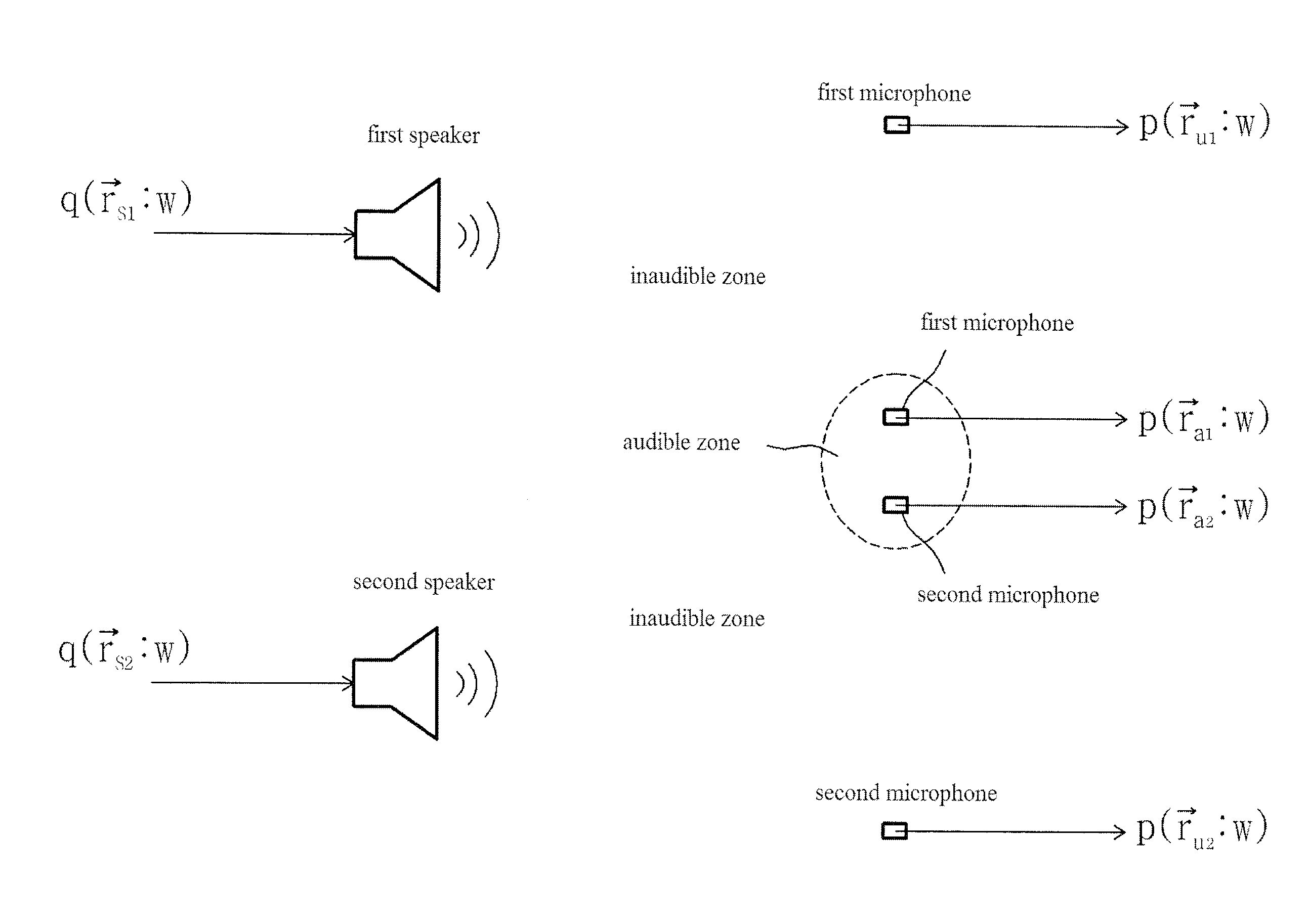
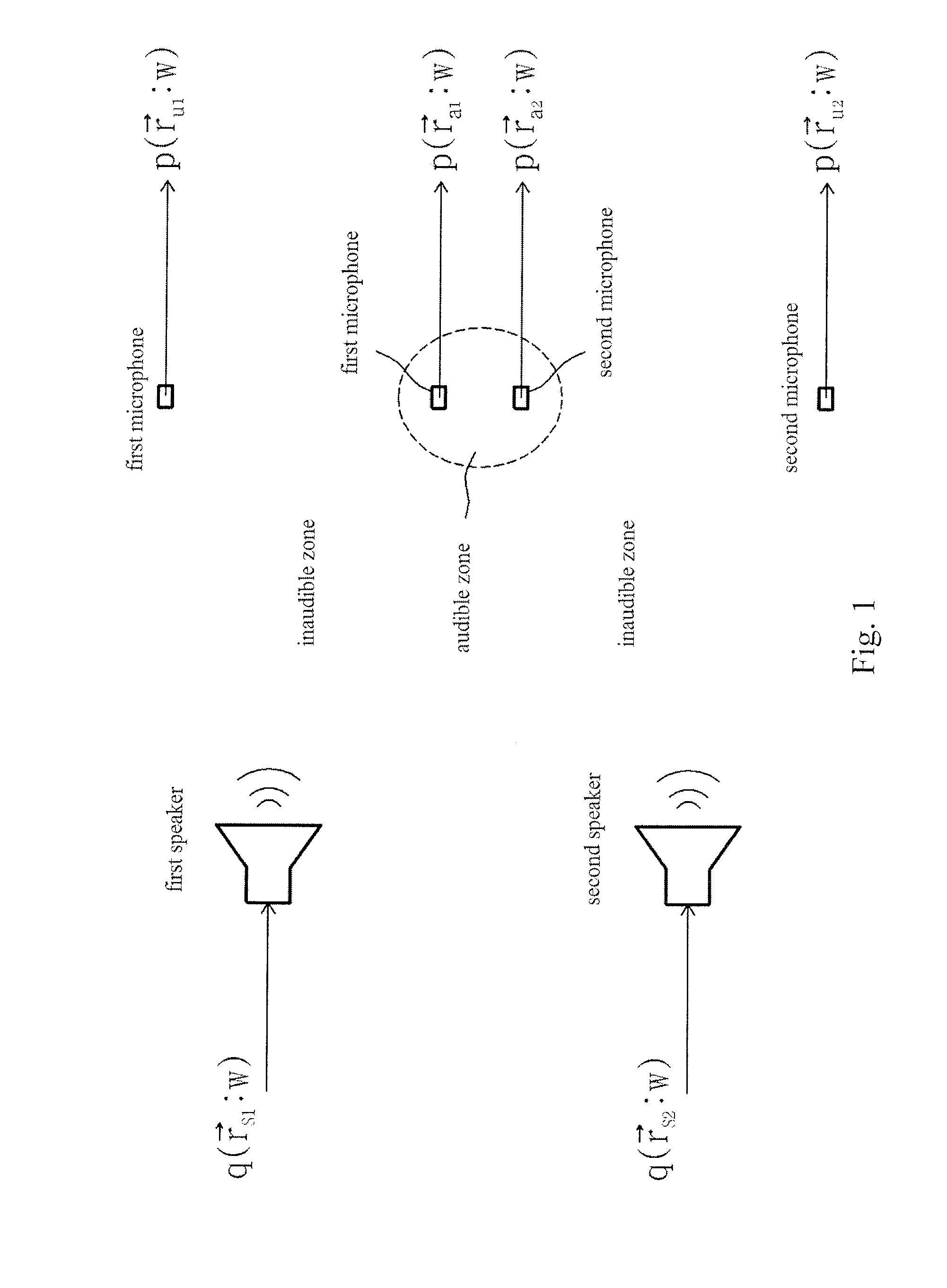
[0084]FIG. 1 is a schematic drawing for explaining the theoretical contents relating to the present invention. FIG. 1 schematically shows an acoustic space. In the acoustic space, the first speaker and the second speaker are installed. The acoustic space is divided into a zone that is selected as an audible zone, where the listener exists (hereinafter, it is called the “audible zone”), and a zone other than audible zone, where the listener does not exist (hereinafter, it is called the “inaudible zone”). In FIG. 1, the audible zone and inaudible zone are schematically distinguished by the circular dotted line. The inaudible zone means practically the total zone other than the zone where the listener exists.

[0085]In the case in which there are the first sound source, the second sound source, . . . , and the Nth sound source in the acoustic space, the sound pressure (p({right arrow over (...


PUM


Abstract

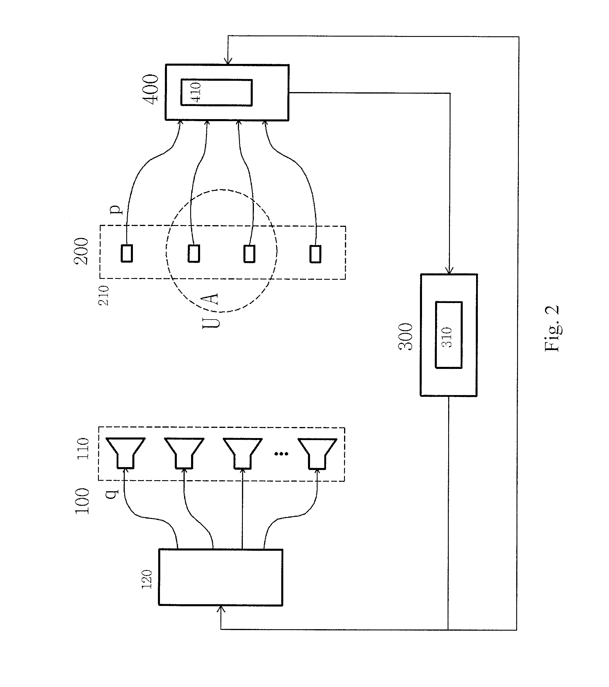
An apparatus for reproducing sound from original source signals, has a control device, a first speaker, and a second speaker. The control device receives first and second original source signals, and controls magnitudes and phases of the received first and second original source signals so that a sound pressure level in a pre-determined zone is higher than a sound pressure level in a zone other than the pre-determined zone, and outputs first and second controlled source signals. The first speaker receives the first controlled source signal and reproduces sound. The second speaker receives the second controlled source signal and reproduces sound. The apparatus according provides a sound environment in which only the person using the sound system enjoys the sound.

Description

BACKGROUND OF THE INVENTION[0001]1. Field of the Invention[0002]The present invention relates to an apparatus for reproducing sound, a method for reproducing sound, a monitor with speakers, and a mobile phone with speakers.[0003]2. Background Information[0004]Sound field control technology using a plurality of sound sources has been generally developed in order to improve the acoustic characteristics at some designated positions in space. However, recently, technology has been developing to improve the acoustic characteristics of a specific zone (i.e. where a listener exists). Sound field control technology using a plurality of sound sources can be categorized into two groups in general. One is an active noise control that reduces sound level of a zone by changing the magnitude / phase input to a plurality of sound sources actively. The other is a control that increases the emitted sound power for a specific angle by changing a gap between sources that are arranged in a specific shape...

Claims


Application Information

Patent Timeline
IPC IPC(8): H04R29/00H04R25/00
CPCH04R2499/11H04R2499/15H04S7/303H04S7/30H04S3/00H04R3/00
Inventor KIM, YANG-HANNCHOI, JOUNG-WOOCHANG, JI-HOPARK, JIN-YOUNGLEE, CHAN-HUI
Owner KOREA ADVANCED INST OF SCI & TECH
Learn More