Optical routing device and optical network using same

a routing device and optical network technology, applied in the field of optical networks, can solve the problems of difficult network modification, high cost, and the likelihood of increasing the density of wavelengths on which different data signals may be transported

Active Publication Date: 2010-11-11
CIENA
View PDF3 Cites 32 Cited by
  • Summary
  • Abstract
  • Description
  • Claims
  • Application Information

AI Technical Summary

Benefits of technology

[0009]By employing optical multicast routing elements and optical blocking elements selectively placed within the network fabric so as to preclude any optical loops in the network or more than one optical path between any two nodes of the network, a network c...

Problems solved by technology

However, they are relatively expensive because, among other reasons, they are relatively complex and incorporate active optical elements.
Furthermore, it is difficult to alter a network after it has been set up using such components.
As technology improves, the wavelengths on which different data signals may be transported are likely to become increasingly densely packed.
Therefore, to change the wavelengths used in a...

Method used


Image

  • Optical routing device and optical network using same
  • Optical routing device and optical network using same
  • Optical routing device and optical network using same

Examples


Embodiment Construction

)

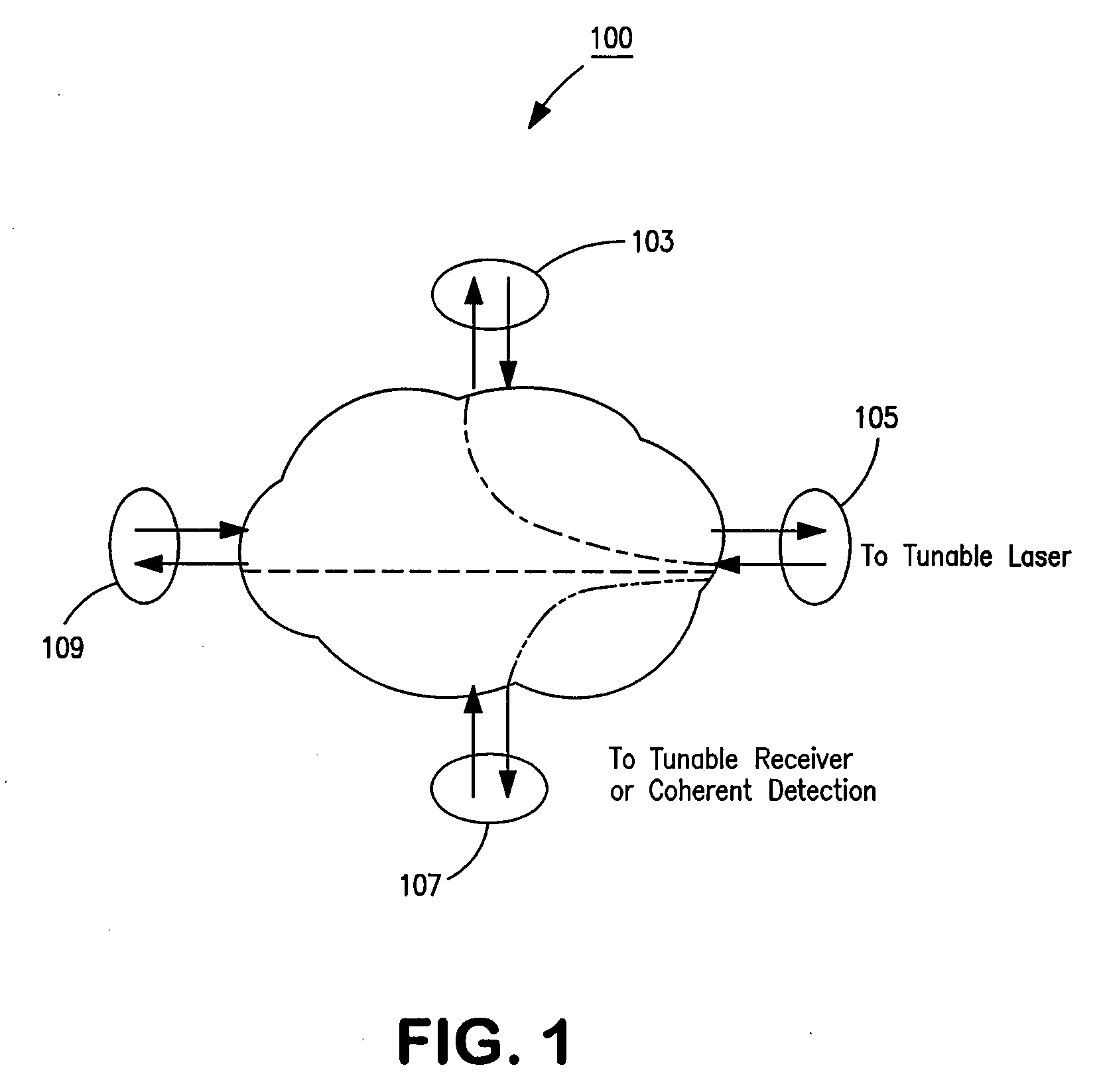
[0017]FIG. 1 is a functional diagram illustrating the basic building block that may be used in accordance with this disclosure to build optical networks at low cost and with minimal design requirements. The element 100 is herein termed an optical multicast element. The optical multicast element 100 comprises a plurality of ports. In this example, the element has four ports 103, 105, 107, 109. However, this is merely exemplary and the element can have any number of ports. Each port is an input / output port. The optical multicast element 100 can accept an input signal at any port and will output that signal at each of the other ports. Thus, an input signal at port 105 is split and provided to each of the other output ports 103, 107, and 109. No portion of the signal returns to the same port.

[0018]While not shown in order not to unnecessarily obfuscate FIG. 1, a second input signal may be provided at port 103, which would be output at ports 105, 107, and 109, a third input signal may b...


PUM


Abstract

The invention pertains to methods, apparatus, and systems optical of networking using tunable receivers, optical blocking elements selectively placed in the network, and optical routing elements comprised of passive elements, such as optical couplers and splitters. The routing elements have a plurality of ports and comprise passive elements such as couplers and splitters configured so that input light received at any port of the element is output from each of the other ports of the element, but not at port at which it was input.

Description

FIELD OF THE INVENTION[0001]The invention pertains to optical networks. More particularly, the invention pertains to techniques and apparatus for implementing optical networks using inexpensive routing components, such as splitters and couplers, rather than more complicated and expensive equipment, such as reconfigurable optical add-drop multiplexers (ROADMs) or optical cross-connects (OXCs).BACKGROUND OF THE INVENTION[0002]Optical networks are becoming increasingly common because of the extremely wide bandwidth that can be supported by optical transmission techniques. Many, if not most, optical networks utilize wavelength division multiplexing (WDM) or dense wavelength division multiplexing (DWDM) in order to maximize the amount of information that can be transported over the network per unit time (i.e., data bandwidth). Like all information networks, switching or routing devices are provided in the network to direct signals between nodes of the network to assure that information o...

Claims


Application Information

Patent Timeline
IPC IPC(8): H04J14/02
CPCH04J14/0204H04J14/0275H04J14/0213H04J14/022H04J14/0286H04J14/0297H04Q11/0005H04Q2011/0015H04Q2011/0016H04Q2011/0018H04J14/0238H04J14/0212H04J14/0267H04J14/0268H04J14/0206
Inventor ZOTTMANN, HARALD
Owner CIENA
Why Eureka
Try Eureka