Communication Method and Radio Communication Terminal

a radio communication terminal and communication method technology, applied in the direction of substation equipment, electrical equipment, connection management, etc., can solve the problems of unstable operation of the radio communication terminal ms located at the cell edge, more difficult to establish a connection with the radio base station bs, so as to achieve stably executed the effect of easy connection

Inactive Publication Date: 2010-11-11
INTERDIGITAL PATENT HLDG INC
View PDF4 Cites 28 Cited by
  • Summary
  • Abstract
  • Description
  • Claims
  • Application Information

AI Technical Summary

Benefits of technology

[0040]According to the characteristic, as described above, the radio communication terminal can stably execute the cell search and the subsequent establishing of the connection, by using the lower frequency band in which the instantaneous value variation and the distance attenuation of the reception power by a so directional beam transmission (beamforming transmission or diversity transmission) are relatively stable.
[0041]The present invention can provide a communication method and a radio communication terminal, which enable easy establishment of a connection with a radio base station by allowing the cell search to be stably executed even when the radio communication terminal is located at the cell edge in a multiband mobile communication system.

Problems solved by technology

Thus, operation of the radio communication terminal MS located at the cell edge is expected to be unstable during the cell search.
When the cell search operation is unstable, it is difficult to establish a connection with the radio base station BS.
Particularly, when the radio communication terminal MS is located in the urban area, when a movement speed of the radio communication terminal MS is high, or in other cases, it is more difficult for the radio communication terminal Ms to establish a connection with the radio base station BS.

Method used


Image

  • Communication Method and Radio Communication Terminal
  • Communication Method and Radio Communication Terminal
  • Communication Method and Radio Communication Terminal

Examples


first embodiment

Overall Schematic Configuration of Mobile Communication System

[0061]FIG. 8 is a schematic diagram showing an overall configuration example of a mobile communication system according to this embodiment.

[0062]The mobile communication system shown in FIG. 8 includes a radio communication terminal MS, a radio base station BS1 and a radio base station BS2. The radio base station BS1 forms a cell C1. The radio base station BS2 forms a cell C2. Note that the mobile communication system employs a multiband mobile communication system while conforming to IEEE802.15e (Mobile WiMAX (registered trademark)). The radio base stations BS1 and BS2 include multiple antenna elements.

[0063]As to a network configuration of the multiband mobile communication system, there are three cases: a case where the network includes only a dual band base station; a case where the network includes the dual band base station and a single band base station; and a case where the network includes only the single band ba...

second embodiment

[0086]In this embodiment, description will be given of a configuration of selecting a connection destination radio base station by considering movement speed of a radio communication terminal MS. Note that, in the following second to fourth embodiments, differences from the first embodiment will be mainly described and repetitive description will be omitted.

(Configuration Example of Radio Communication Terminal)

[0087]FIG. 12 is a functional block diagram showing a configuration example of the radio communication terminal MS according to this embodiment.

[0088]The radio communication terminal MS is different from the radio communication terminal MS shown in FIG. 10 in including a movement speed measurement unit 17 configured to measure movement speed v of the radio communication terminal MS. The movement speed measurement unit 17 measures movement speed by using, for example, GPS (Global Positioning System), a gyro sensor or the like.

[0089]The movement speed v measured by the movement...

third embodiment

[0097]In this embodiment, description will be given of a configuration in which a radio communication terminal MS select a connection destination radio base station by considering a reception power from each radio base station.

(Configuration Example of Radio Communication Terminal)

[0098]FIG. 14 is a functional block diagram showing a configuration example of the radio communication terminal MS according to this embodiment.

[0099]The radio communication terminal MS is different from the radio communication terminal MS shown in FIG. 10 in including a reception power measurement unit 18 configured to measure reception powers from the radio base stations BS1 and B52.

[0100]The reception power measured by the reception power measurement unit 18 is notified to the communication controller 15. Based on the notified reception power, the communication controller 15 controls the first determination unit 13 and the second determination unit 14 and selects the connection destination radio base st...


PUM


Abstract

Even when being located at cell edge in a multiband mobile communication system, a radio communication terminal, is allowed to stably execute cell search so as to easily establish a connection with a radio base station. The radio communication terminal according to the present invention includes: a first determination unit 13 configured to determine whether or not a broadcast map can be received from a plurality of radio base stations; a second determination unit 14 configured to determine whether or not an AAS diversity map can be received trom the radio base stations in ascending order of used frequency bands, when it is determined that the broadcast map cannot be received; and a communication controller 15 configured to select a radio base station, which is determined to be a radio base station from which the AAS diversity map can be received, as a connection destination radio base station, and to communicate with the selected radio base station.

Description

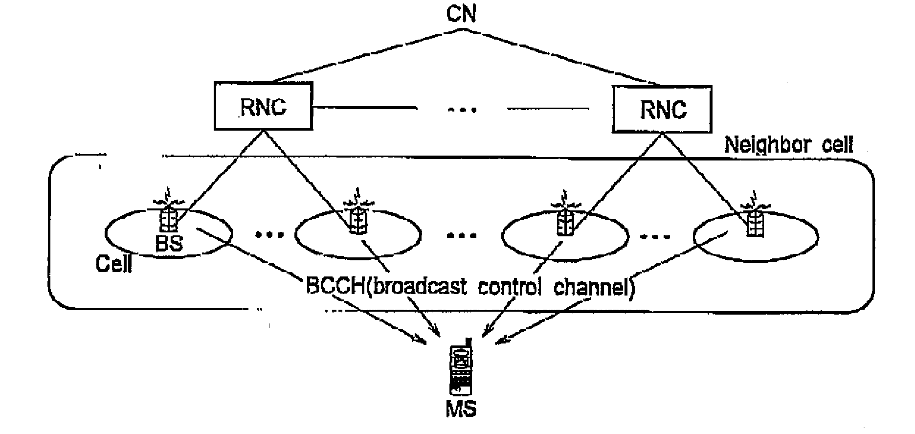
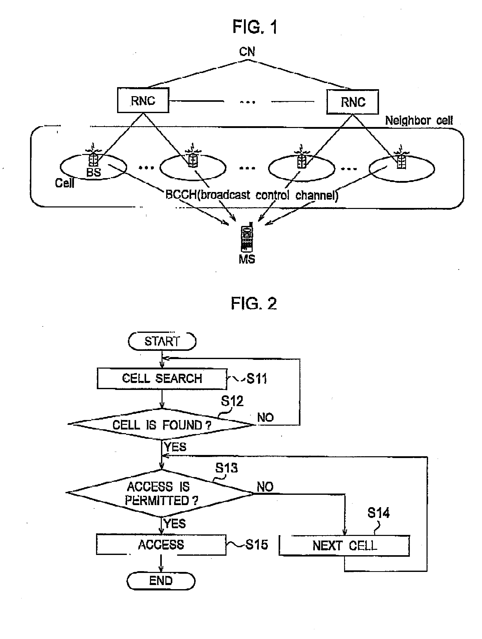
TECHNICAL FIELD[0001]The present invention relates to a communication method and a radio communication terminal for selecting a connection destination radio base station from multiple radio base stations capable of using frequency bands different trom each other and for communicating with the selected radio base station.BACKGROUND ART[0002]FIG. 1 shows a schematic configuration of a conventional mobile communication system. As shown in FIG. 1, the conventional mobile communication system includes a radio communication terminal MS, radio base stations BS, radio network controllers RNC and a core network CN. The radio communication terminal MS executes cell search to search for a connectable cell (radio base station) among multiple cells at the time of network entry or handover.[0003]FIG. 2 shows an example of a process procedure of the cell search executed by the radio communication terminal MS in the mobile communication system shown in FIG. 1. In Step S11 of FIG. 2, the radio commu...

Claims


Application Information

Patent Timeline
Patent Type & Authority Applications(United States)
IPC IPC(8): H04W72/00H04W8/00H04W48/10H04W48/16H04W48/20H04W76/02H04W88/08
CPCH04W8/005H04W48/20H04W48/16H04W48/10H04W48/08H04W88/10
Inventor TODA, TAKESHINAKAYAMA, TAKUJOKO, SHINGO
Owner INTERDIGITAL PATENT HLDG INC
Why Eureka
Try Eureka