Automated Eyedrop Delivery System with Eyelid Retracting Legs

a delivery system and eyelid technology, applied in signalling systems, physical therapy, instruments, etc., can solve the problems of eye drop solution being frequently wasted, users have trouble with dispensing eye drops from standard dispensing bottles, and drop to miss the eye and land on a closed lid

Active Publication Date: 2010-11-11
MARX ALVIN J
View PDF81 Cites 70 Cited by
  • Summary
  • Abstract
  • Description
  • Claims
  • Application Information

AI Technical Summary

Benefits of technology

[0009]Another object of the invention is to provide a lid spreading eye drop bottle holder that allows the user to easily attach and detach a standard eye drop bottle to the lid spreading device.
[0012]Yet another object of the invention is to provide a lid spreading eye drop bottle holder that is inexpensive to manufacture.
[0016]In accordance with an embodiment of the invention, there is disclosed a first embodiment of an eye drop bottle holder with resilient legs comprising: an inverted U-shaped shape made from resilient injection molded plastic, the top portion of said inverted U-shape including a centrally located aperture and downwardly facing collar, said collar having internal threads that match the external threads of a standard eye drop bottle containing eye drop solution, the right and left leg of said U-shape each terminating in an outwardly disposed J-shape, the underside of said J-shape covered by a soft rubber-like pad, so that when a user screws said standard eye drop bottle into said threaded collar, the dispensing tip of said eye drop bottle can come into close proximity of the user's eye, and so that the user can cause his or her eye lid to remain open by using the fingers of one hand to squeeze said right and left legs together, then placing the said rubber-like pad of one leg on his or her upper ridge of the orbital eye socket and the said second rubber-like pad of the second leg on the lower ridge of his or her orbital eye socket and then releasing the legs thereby causing the flesh of the user's upper and lower eyelids to be spread apart from each other and remain spread during a standard eye drop solution dispensing event.

Problems solved by technology

Many users have trouble with dispensing eye drops from standard dispensing bottles.
The user has a tendency to blink when the drop is about to enter the eye, causing the drop to miss the eye and land on a closed lid.
Therefore, eye drop solution is frequently wasted due to the user blinking during the attempted application and the user ends up with eye drop solution streaming down his or her face.
However, no attempt is made to hold the eyelid open.
It is not designed to be used by a user of eye drop solution.
None of the above cited inventions safely holds the user's eyelids open while dispensing eye drops from a standard eye drop bottle.
Additionally, none of the above mentioned patents allows the user to dispense a portioned amount of eye drop solution in an automatic and repeatable fashion.

Method used


Image

  • Automated Eyedrop Delivery System with Eyelid Retracting Legs
  • Automated Eyedrop Delivery System with Eyelid Retracting Legs
  • Automated Eyedrop Delivery System with Eyelid Retracting Legs

Examples


embodiment 900

[0046]FIG. 8 is a top plan view of the second preferred embodiment 900 in the open position.

[0047]FIG. 9 is a top plan view of the second preferred embodiment 900 in the closed position.

[0048]FIG. 10 is a front plan view of the second preferred embodiment 900 of the invention.

[0049]FIG. 11 is a front plan view of the second preferred embodiment 900 of the invention with the bottle 928 and cap 950 included.

[0050]FIG. 12 is a front plan view of the second preferred embodiment 900 of the invention with the bottle 928 in place and the cap 950 removed.

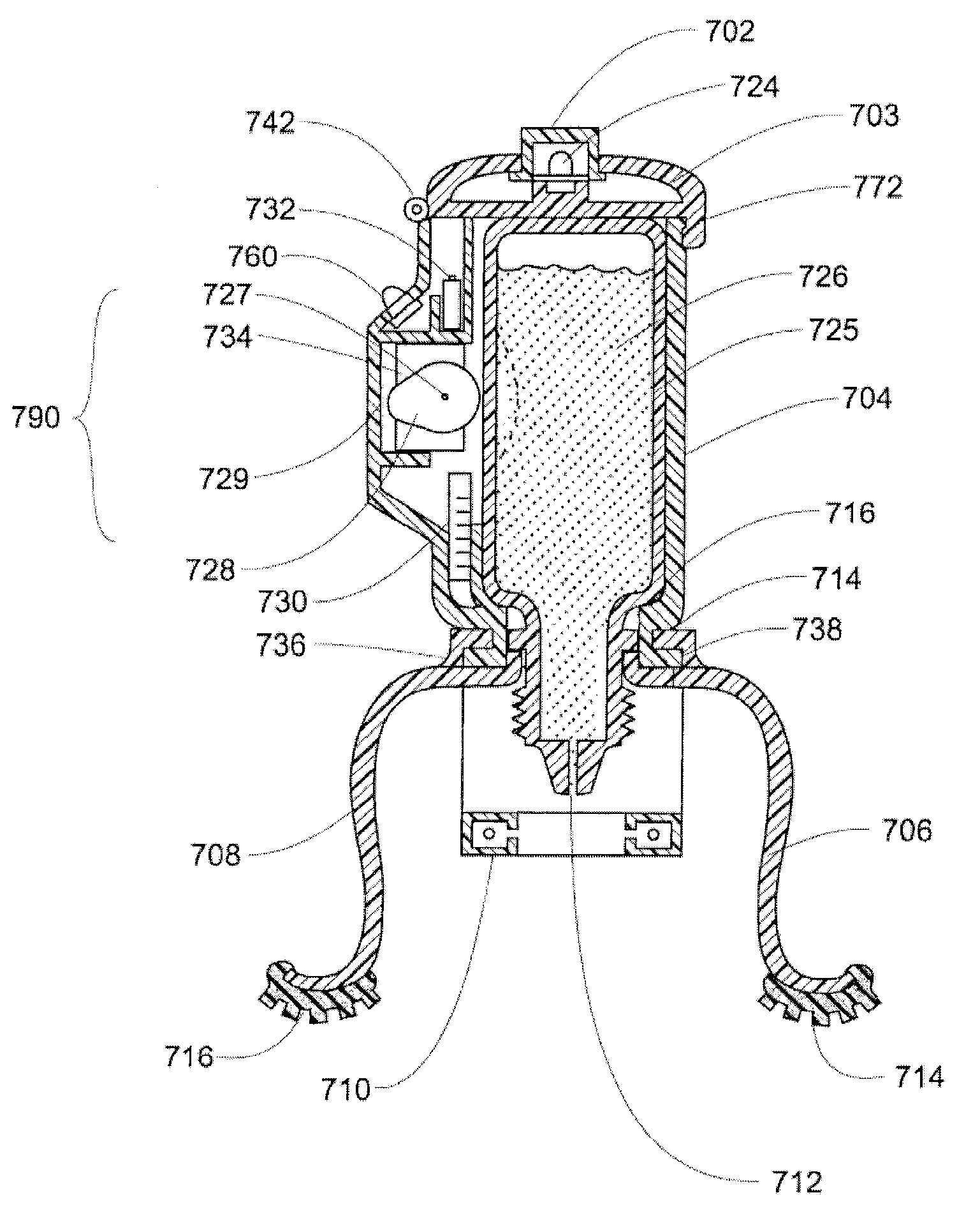
[0051]FIG. 13 shows a third preferred embodiment 700 of the invention. This embodiment 13 may be considered a preferred embodiment because it is the most fool proof of the above described embodiments. With the third embodiment the user simply has to press on top button 702 and a predetermined amount of solution automatically is dispensed into the user's eye. The resilient leg portion 795 of this embodiment works the same was as described in...

third embodiment

[0058]FIG. 20 shows a schematic view of the components of the third preferred embodiment as described above. FIG. 21 shows a block diagram of the steps involved in a person using the third embodiment as described above.

[0059]FIG. 19 shows a fourth preferred embodiment 780 of the present invention which is similar to the third embodiment 700 except that the droplet sensing photo-interrupter 710 is not included. In this embodiment 780, The user presses on dispense button 702 and when he or she feels the drop of solution hit the eye, he or she removes their finger from the dispense button 702 thereby causing the reversing action of electro-mechanical assembly 790, described in the third embodiment, to take place and bring the cam 728 back to its start position.


PUM


Abstract

An eye drop bottle holder with resilient legs includes an inverted U-shaped member made from resilient injection molded plastic. The top portion of the inverted U-shaped member includes an eye drop bottle holder. The right and left leg of the U-shape each terminate in an outwardly disposed J-shape covered by a soft rubber-like pad. The user can attach an eye drop bottle to the inverted U-shaped member so that the dispensing tip of the bottle is in close proximity the user's eye. The user can cause his or her eye lid to remain open by squeezing the right and left legs together, then placing the pads on the upper and lower eye orbit, then releasing the legs causing the flesh of the user's eyelids to be spread apart. In a preferred embodiment, an electro-mechanical assembly can automatically press on the side wall of the bottle to cause a predetermined amount of solution to be dispensed. An LED light flashes (is either activated or deactivated) to show the user that a dispensing event has taken place.

Description

CROSS REFERENCE TO RELATED APPLICATIONS[0001]This Application claims the benefit under Title 35 United States Code §120 as a Continuation-in-Part of co-pending U.S. patent application Ser. No. 12 / 319,908, filed Jan. 12, 2009; which itself further claims the benefit under Title 35 United States Code §119(e) of U.S. Provisional Patent Application Ser. No. 61 / 026,471, filed Feb. 5, 2008; U.S. Provisional Patent Application Ser. No. 61 / 075,768, filed Jun. 26, 2008; U.S. Provisional Patent Application Ser. No. 61 / 086,436, filed Aug. 5, 2008; and U.S. Provisional Patent Application Ser. No. 61 / 097,153, filed Sep. 15, 2008; the full disclosures of which are each incorporated herein by reference.BACKGROUND OF THE INVENTION[0002]1. Field of the Invention[0003]This invention relates generally to the field of eye drop dispensing devices and more specifically to an eye drop bottle holder with resilient legs.[0004]2. Description of the Related Art[0005]Devices for dispensing eye drop solutions a...

Claims


Application Information

Patent Timeline
Patent Type & Authority Applications(United States)
IPC IPC(8): A61F9/00A61M35/00G08B5/00
CPCA61F9/0026A61F9/0008
Inventor MARX, ALVIN J.
Owner MARX ALVIN J
Why Eureka
Try Eureka