Method for removing a contamination layer from an optical surface and arrangement therefor as well as a method for generating a cleaning gas and arrangement therefor

a technology of optical surface and contamination layer, which is applied in the direction of cleaning using liquids, instruments, therapy, etc., can solve the problems of unpredictability of the amount of material removed from the contamination layer by the cleaning gas, unwanted reflection loss, etc., and achieve the effect of reducing or avoiding damage to the optical surfa

Active Publication Date: 2010-11-18
CARL ZEISS SMT GMBH +1
View PDF14 Cites 30 Cited by
  • Summary
  • Abstract
  • Description
  • Claims
  • Application Information

AI Technical Summary

Benefits of technology

[0008]It is an object of the invention to provide a method for at least partially removing a contamination layer from an optical surface of an EUV-reflective element, a method for generating a cleaning gas, as well as a corresponding cleaning arrangement and a corresponding cleaning gas generation arrangement, all of which are suitable for reducing or avoiding damage to the optical surface of the EUV-reflective element which may otherwise be caused by the cleaning process.

Problems solved by technology

The formation of the contamination layer is triggered by radiation-induced cracking of hydrocarbon molecules, the presence of which cannot be avoided even though the compartments of the EUV-lithography system are operated under vacuum conditions.
In general, the amount of material removed from the contamination layer by the cleaning gas cannot be precisely determined.
In case that the cleaning time is too short, part of the contamination layer will not be removed from the optical surface, causing an unwanted reflection loss even after the cleaning.
As the optical surface in general also reacts with the cleaning gas, an irreversible contamination is caused on the optical surface in a low amount per cleaning cycle.

Method used


Image

  • Method for removing a contamination layer from an optical surface and arrangement therefor as well as a method for generating a cleaning gas and arrangement therefor
  • Method for removing a contamination layer from an optical surface and arrangement therefor as well as a method for generating a cleaning gas and arrangement therefor
  • Method for removing a contamination layer from an optical surface and arrangement therefor as well as a method for generating a cleaning gas and arrangement therefor

Examples


Embodiment Construction

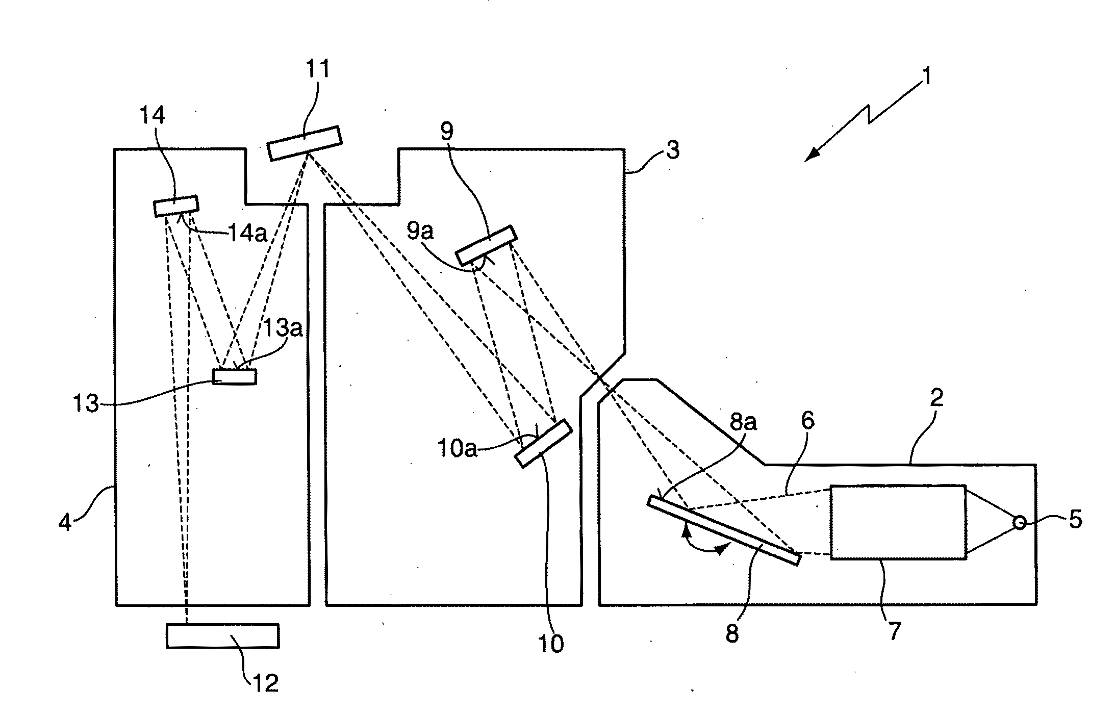
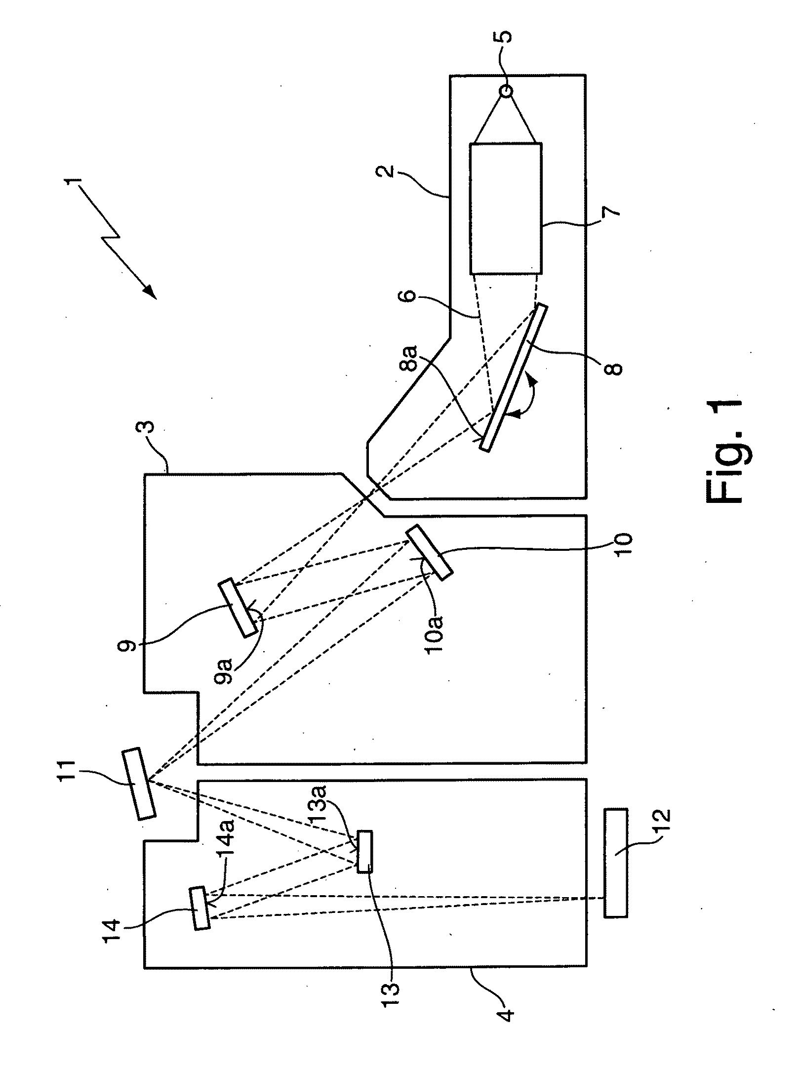
[0059]FIG. 1 shows a schematic representation of a EUV-lithography system which is designed for manufacturing highly integrated semiconductor devices. The EUV-lithography system 1 comprises a beam shaping system 2, an illumination system 3 and a projection system 4, each of which is arranged in a separate vacuum compartment. The beam shaping system 2 comprises a EUV light source 5 which may be implemented as a plasma source or as a synchrotron source and emits EUV light which forms an optical path 6 through the EUV-lithography system 1. The EUV light emitted in a wavelength range of between 5 nm and 20 nm from the EUV light source 5 is first fed to a collimator 7 and subsequently, the desired operating wavelength for the exposure process (typically 13.5 nm) is selected by adjusting the incidence angle (see the double-headed arrow) of the EUV light which impinges on an optical surface 8a of a monochromator 8. The collimator 7 and the monochromator 8 are in general implemented as refl...


PUM

PropertyMeasurementUnit
wavelength rangeaaaaaaaaaa
thicknessaaaaaaaaaa
thicknessaaaaaaaaaa

Abstract

The invention is directed to a method for at least partially removing a contamination layer (15) from an optical surface (14a) of an EUV-reflective optical element (14) by bringing a cleaning gas into contact with the contamination layer. In the method, a jet (20) of cleaning gas is directed to the contamination layer (15) for removing material from the contamination layer (15). The contamination layer (15) is monitored for generating a signal indicative of the thickness of the contamination layer (15) and the jet (20) of cleaning gas is controlled by moving the jet (20) of cleaning gas relative to the optical surface (14a) using this signal as a feedback signal. A cleaning arrangement (19 to 24) for carrying out the method is also disclosed. The invention also relates to a method for generating a jet (20) of cleaning gas and to a corresponding cleaning gas generation arrangement.

Description

CROSS REFERENCE TO RELATED APPLICATION[0001]This application is a continuation application of international patent application PCT / EP 2007 / 009593, filed Nov. 6, 2007, designating the United States and the entire content thereof is incorporated herein by reference.FIELD OF THE INVENTION[0002]The invention relates to a method for at least partially removing a contamination layer from an optical surface of an EUV-reflective optical element by bringing a cleaning gas, preferably comprising atomic hydrogen, into contact with the contamination layer. The invention also relates to a cleaning arrangement for carrying out the method. A method is also disclosed for generating a jet of cleaning gas, preferably comprising atomic hydrogen, to be directed to a contamination layer on an optical surface of an EUV-reflective optical element. In addition, a corresponding cleaning gas generation arrangement as well as an EUV-lithography system are presented.BACKGROUND OF THE INVENTION[0003]Lithography...

Claims


Application Information

Patent Timeline
Patent Type & Authority Applications(United States)
IPC IPC(8): B08B7/00B08B5/02
CPCB08B7/00B08B5/02G03F7/70925
Inventor EHM, DIRK HEINRICHSTORM, ARNOLDMOORS, JOHANNES HUBERTUS JOSEPHINAWOLSCHRIJN, BASTIAAN THEODOORSTEIN, THOMASSLIGTE, EDWIN TE
Owner CARL ZEISS SMT GMBH
Why Eureka
Try Eureka