Thin film solar cell and fabrication method thereof

Inactive Publication Date: 2010-11-18
TSAI CHIN YAO
View PDF20 Cites 0 Cited by
  • Summary
  • Abstract
  • Description
  • Claims
  • Application Information

AI Technical Summary

Benefits of technology

[0009]Accordingly, one embodiment of the present invention provides a thin film solar cell capab

Problems solved by technology

It is dangerous for users, and the th

Method used


Image

  • Thin film solar cell and fabrication method thereof
  • Thin film solar cell and fabrication method thereof
  • Thin film solar cell and fabrication method thereof

Examples


Example

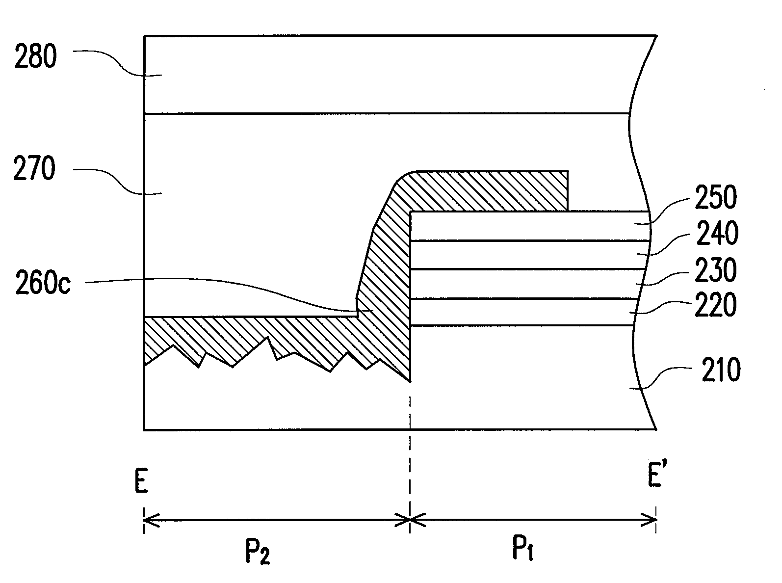
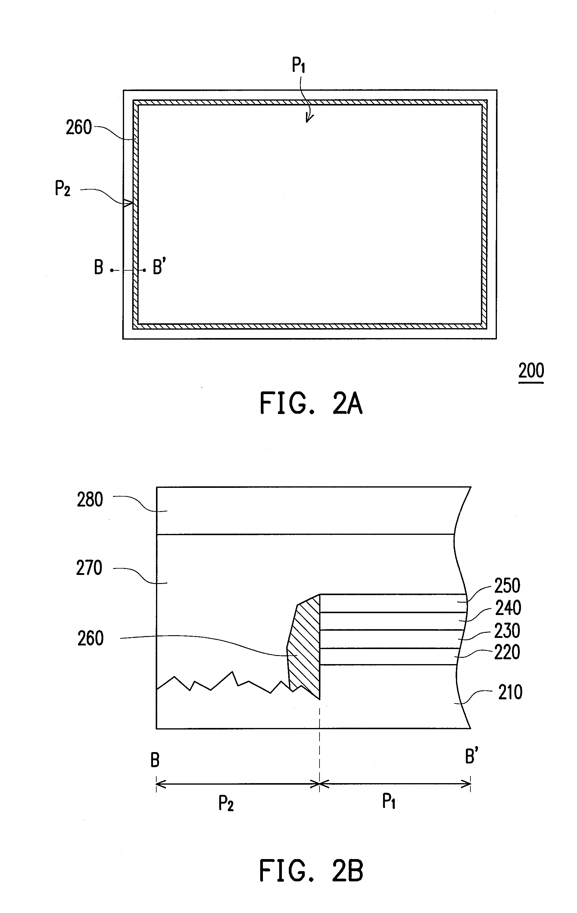
[0037]FIG. 2A is a top view of a thin film solar cell according to an embodiment consistent with the present invention. FIG. 2B is a cross-sectional view of the thin film solar cell along the line BB′ in FIG. 2A. For convenience of description, FIG. 2A simply illustrates the top view of films on a first substrate in FIG. 2B but ignores a second substrate and an adhesion layer between the first substrate and the second substrate. Referring to FIG. 2A and FIG. 2B, the thin film solar cell 200 of the present embodiment has an active area P1 and a dead area P2. Furthermore, the thin film solar cell 200 includes the first substrate 210, a first conductive 220, an photovoltaic layer 230, a second conductive layer 240, a first passivation layer 250, and a second passivation layer 260.

[0038]The first conductive layer 220 is disposed on the first substrate 210 and located in the active area P2, as shown in FIG. 2B. In the present embodiment, the first substrate 210 may be a transparent subst...


PUM


Abstract

A thin film solar cell having an active area and a dead area is provided. The thin film solar cell includes a first substrate, a first conductive layer, an photovoltaic layer, a second conductive layer, a first passivation layer, and a second passivation layer. The first conducting layer, the photovoltaic layer, the second conductive layer, and the first passivation layer are respectively disposed on the first substrate, the first conductive layer, the photovoltaic layer, and the second conductive layer, and all of them are located in the active area. The second passivation layer is disposed on a peripheral of the photovoltaic layer and located in the dead area, so as to avoid the photovoltaic layer from contacting with moisture in air. A fabrication method of the thin film solar cell is also provided.

Description

CROSS-REFERENCE TO RELATED APPLICATION[0001]This application claims the priority benefit of Taiwan application serial no. 98115711, filed on May 12, 2009. The entirety of the above-mentioned patent application is hereby incorporated by reference herein and made a part of specification.BACKGROUND OF THE INVENTION[0002]1. Field of the Invention[0003]The present invention generally relates to a solar cell and a fabrication method thereof, and more particularly, to a thin film solar cell capable of avoiding infiltration of moisture in air and a fabrication method thereof.[0004]2. Description of Related Art[0005]FIG. 1A is a top view of a conventional thin film solar cell. FIG. 1B is a cross-sectional view of the thin film solar cell along the line AA′ in FIG. 1A. For convenience of description, FIG. 1A simply illustrates the top view of films on a first substrate in FIG. 1B but ignores a second substrate and an adhesive between the first substrate and the second substrate. Referring FIG...

Claims


Application Information

Patent Timeline
IPC IPC(8): H01L31/00H01L31/18
CPCH01L31/02167Y02E10/50H01L31/048H01L31/0392H01L31/03923H01L31/03925H01L31/049Y02E10/541
Inventor TSAI, CHIN-YAO
Owner TSAI CHIN YAO
Why Eureka
Try Eureka